

I bought my URM-25F signal generator from George Rancourt at Deerchester many years ago.

I hadn’t used it much until the band-switch mechanism on my HP-606A froze up. The RF portion of the URM-25F worked fine, but the audio oscillator would cut out after a half-hour or more.

This is the classic symptom of leaky capacitors in the AF oscillator. I think the capacitors are hermetically-sealed paper-in-oil, and they look to be the original ones. I tested a few for leakage, and they all were leaky. Fortunately the oil-filled power supply filter capacitor (the large silver component on the left of the photo) was still good. Perhaps it actually has a plastic film dielectric rather than paper.

Replacing all the paper capacitors involves pulling the oscillator turret and bridge assembly from the front panel. This involves disconnecting a number of wires and shaft couplers.
I followed the procedure in Section 7 Paragraph 17 of a copy of the Navy manual (Navships 92495) that I bought from W7FG manuals (now Vintage Manuals). Vintage Manuals no longer seems to offer a paper copy, but Navships 92495 is available from BAMA. BAMA also has a number of manuals for other variants of the URM-25.
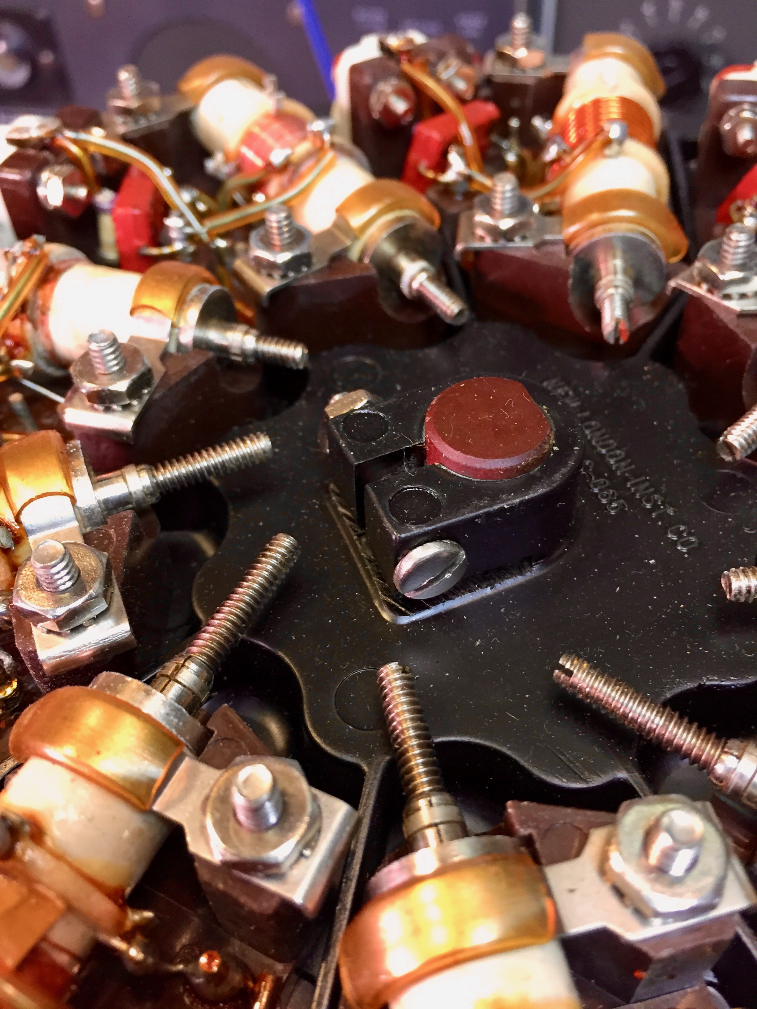
I took lots of photos along the way to help reconnected everything. The procedure starts with disconnecting the three leads from the terminal board in the photo above.

Unsolder the ground lead from the lug adjacent to the attenuator.

Unsolder the step attenuator lead from terminal board TB101.

Unsolder the resistor from the HIGH RF output connector.

Unsolder the three tube heater leads from the feedthrough capacitor.

Unsolder the heater ground leads from the ground lug near the feedthrough capacitor.

Unsolder the red B+ lead from the feedthrough capacitor.

Unsolder the red and white B+ lead from the RF choke.

Loosen the couplings on the function switch,

the modulation level control,

the microvolts control,

and the tuning shaft. I had to pull V103 to get to everything.
Loosen the clamp screw on the turret. Note the position of the turret on the shaft; replace it at the same depth during reassembly.

Loosen the set-screw on the turret shaft cam.

Remove the four 10-32 screws at the base of the turret assembly. I couldn’t do it without a right-angle screwdriver, and there wasn’t room for a ratcheting one. So this was a tedious task.

Another painful one.

I was able to remove this one with an ordinary straight-bladed screwdriver.


The final screw.

This one was already missing.

Lift the bridge assembly away from the panel. Be careful to lift the cam along with the bridge assembly to avoid damage to switch S101, which is visible just below the bearing at the top of the bridge assembly.

I put a short across the power supply filter capacitor. Oil-filled capacitors are notorious for dielectric absorption, so even after being discharged they might regain enough charge to bite you.

A view of the RF deck.

The underside of the RF deck.

Here’s a view of the tuning capacitor.

The audio oscillator bridge assembly. I’ve already removed one of the paper-in-oil capacitors.


Here I’ve started replacing a few of them.

It was a bit of a challenge getting in beneath the tangle of wires from the harness, at the lower right of this photo.

There are only two capacitors that need to be replaced on the RF deck - a Black Beauty and a paper-in-oil.

I replaced them with new yellow polyester film caps.

There is an electrolytic bypass cap underneath the RF deck that needs to be replaced.

I restuffed it. Keeping the original mounting seemed like the easiest course of action.
I followed the reassembly instructions and miraculously it all worked when I was done.