

I went to use my Lambda model 26 high voltage power supply a few months back and found it not working.

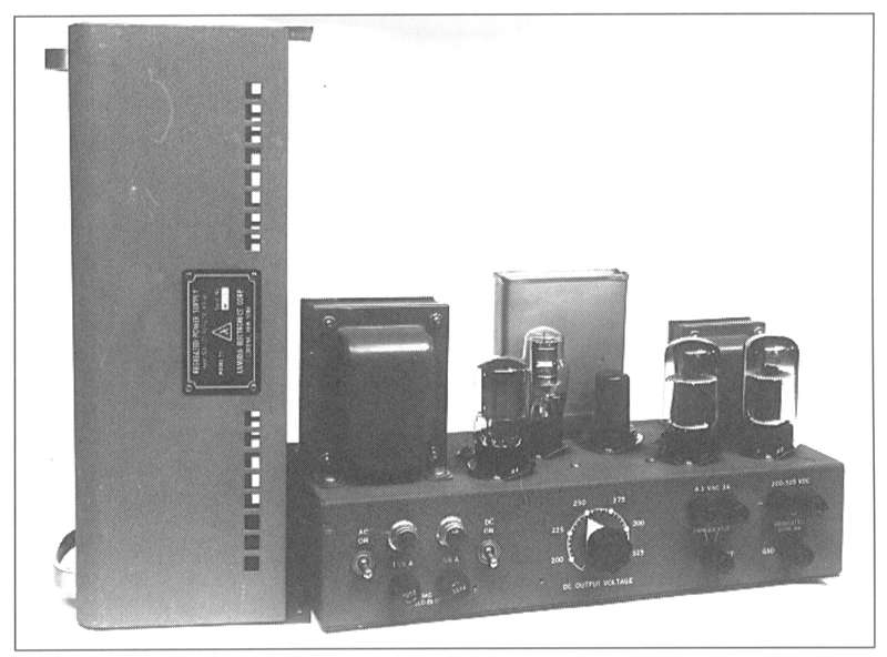
It's a nice vacuum tube power supply, with outputs of 6.3 volts AC for filaments and adjustable high voltage from 100 volts to 200 volts DC at up to 100 mA. The photo above is without the cover.


Lambda built this thing to outlast the pyramids. That big box on the top between the power transformer and the filter choke is a four-section oil filled capacitor. The bypass capacitors are oil-filled, too.

I found some time to work on it this weekend, and found the HV output was about -70 volts, regardless of the output voltage setting. I thought I must have made a mistake in my measurement as I didn't expect the design to have any negative voltages. I don't have a manual or schematic for it, so I was troubleshooting blind.
I did find a schematic for a Lambda 25 power supply over on ARF. It's a lower current version, but aside from the output tubes I thought the designs would be similar.
Here's a photo of one from Alan Douglas' book on tube testers and test equipment.
I made a visual check. All the filaments were lit, and the OA3 VR tube was lit a nice orange, so I concluded that the B+ supply was working. I visually checked the AC line and the B+ fuses and they looked fine.
I posted on ARF asking for a scan of the schematic and describing the trouble. Alan Douglas said he thought the -70 volts was the negative supply for the VR tube. I was skeptical since the minumum output voltage of the supply is so high (100 volts) that it doesn't seem necessary to have a negative voltage supply for the regulator circuitry.
However, I went back to the bench today and took a closer look, and noticed that my model 26 had an extra tube compared to the model 25. There are two rectifier tubes: a 5U4 and a 6X5. Aha! That 6X5 must be for the negative supply! And yes, the -70 volt measurement of the output wasn't a fluke - the output really was sitting at about -70 volts.
OK, so with a negative supply, just because the OA3 is lit doesn't mean that there is B+ to the pass tubes. I suspected the B+ fuse or fuse holder. A check with the multimeter showed 500 volts DC on one side of the fuse holder and 0 volts on the other. I pulled the fuse and this time checked it for continuity with my multimeter. Sure enough, the fuse was open, though visually it appears to have continuity.

It's only a 1/8 amp fuse, so if it had blown I expected to see nothing left of the fuse element. Perhaps it didn't blow but just opened up due to corrosion or vibration.
Anyway, thanks to Alan for pointing me in the right direction.