

The styling of the Precision Apparatus Company E-200-C signal generator has always appealed to me.

For an economical service-grade instrument, it’s also well designed and crafted.
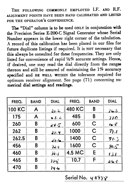
Precision supplied a hand-calibrated reference frequency chart with each instrument as part of their “Servicing by Signal Substitution” instruction booklet. Fortunately my example came with the original booklet.
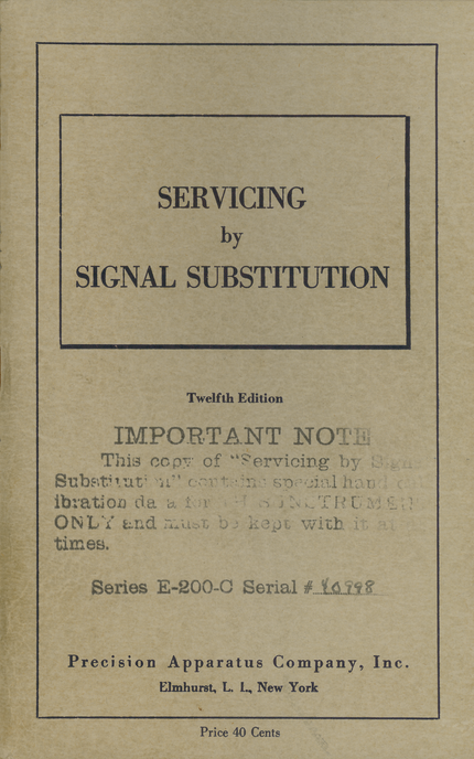
The net doesn’t seem to have any complete scanned copies of Precision's“Servicing by Signal Substitution” booklet. I’ve scanned mine and put it up in my Liberated Manuals and Books archive: G. N. Goldberger and V. I. Robinson, “Servicing by Signal Substitution”.

The booklet came in this envelope, along with …


… this guarantee card.
I recently restored my Precision E-200-C. Here’s the story.

I’ve already cut out the paper capacitors in the AC line filter.

I replaced them with Y-rated safety caps.

I replaced the paper caps in the audio sections with modern polyester film capacitors.

The band switch arrangement is pretty unique. Precision advertised it as their “Unit-Oscillator” construction.

As a result, there a couple of paper capacitors that are a little difficult to replace.

It’s important to preserve the lead dress to keep the generator in calibration.

Here I’ve replaced capacitor “C” on the schematic with a new one. (It doesn’t have a number on the schematic, it’s just “C”.)

Here I’ve unsoldered one lead of C7.

The other end isn’t too bad to get to.


The heater and B+ cloth-covered wiring is all nicely laced.

New capacitors for the audio oscillator section, C10 and C11.

Rather than remove the electrolytic can to re-cap it, I left it in place but cut off the top with a hobby razor saw.

I then drilled some holes in the base for the leads of the new capacitors ...

… and soldered them to the old terminals from below. That way I don’t have to disturb the old wiring. Later, I cleaned out the goop from the top of the can and epoxied it back on.

The dial is peened to the shaft. You aren’t going to slip this dial to adjust the calibration!

Presumably Precision did this so no one would accidentally destroy the hand-calibration made at the factory.

The insulation on the original coax cable was cracking, so I replaced it with Belden 8259 coax (it’s a type of RG-58/A). I recycled the original alligator clips and their fabric-covered wire.

I made up a cable from a Switchcraft 2501F connector to a BNC. I use it to connect my frequency counter to the high-level RF output of the E-200-C.
All done!