

I have a batch of three RCA WV-98C VTVMs on my bench for restoration.

They aren’t the easiest VTVMs to work on. The three meters are from three different production runs: K114, K117, and L60.
I started by removing the meter and the front panel.

This leaves the lower support bracket still blocking access. I removed it by loosening the control nuts on the range and function switches.
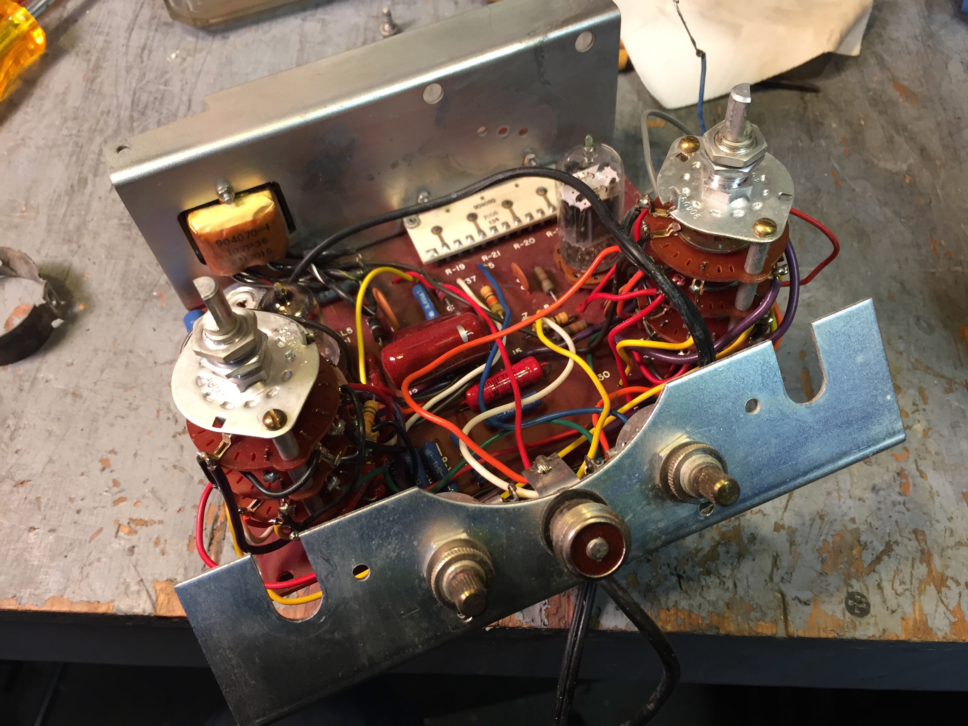
There are still a number of wires between the lower support bracket and the PCB.

I removed the nuts on the Zero and Ohms controls and then unsoldered the wires from the Amphenol connector.

I fed the ground clip wire through the bracket to get enough slack to set it aside. In this example, I had already cut off the line cord as the insulation was cracked at the Heyco strain relief clip.

For the other units, I used some cheap Heyco pliers to remove the strain relief.

I then fed the line cord through the hole to make slack for the bracket.

I could have left the potentiometers mounted on the bracket, as they were still in the way and so I unsoldered them from the PCB.

This layout diagram was really useful in locating the wires on the solder side of the PCB. The top of the PCB has silk-screened numbers where the wires connect to the board, and the diagram annotates the solder side with those numbers.
I don’t remember where I got this diagram. It’s much more legible than any of the PDF manuals for the WV-98C that I have. I might have scanned it from my paper copy of the manual.

I loosely remounted the pots on the lower support bracket, so I wouldn’t get them mixed up.

The range and function switches are mounted directly to the PCB. There’s a good bit of wiring from the switch decks to the PCB, making it difficult to replace the resistors in the range divider.

I plan to remove the switches from the PCB. Fortunately Jim (rja2907@comcast.net on the Antique Radio Forum) provided a copy of the assembly manual for the kit version of the WV-98C.

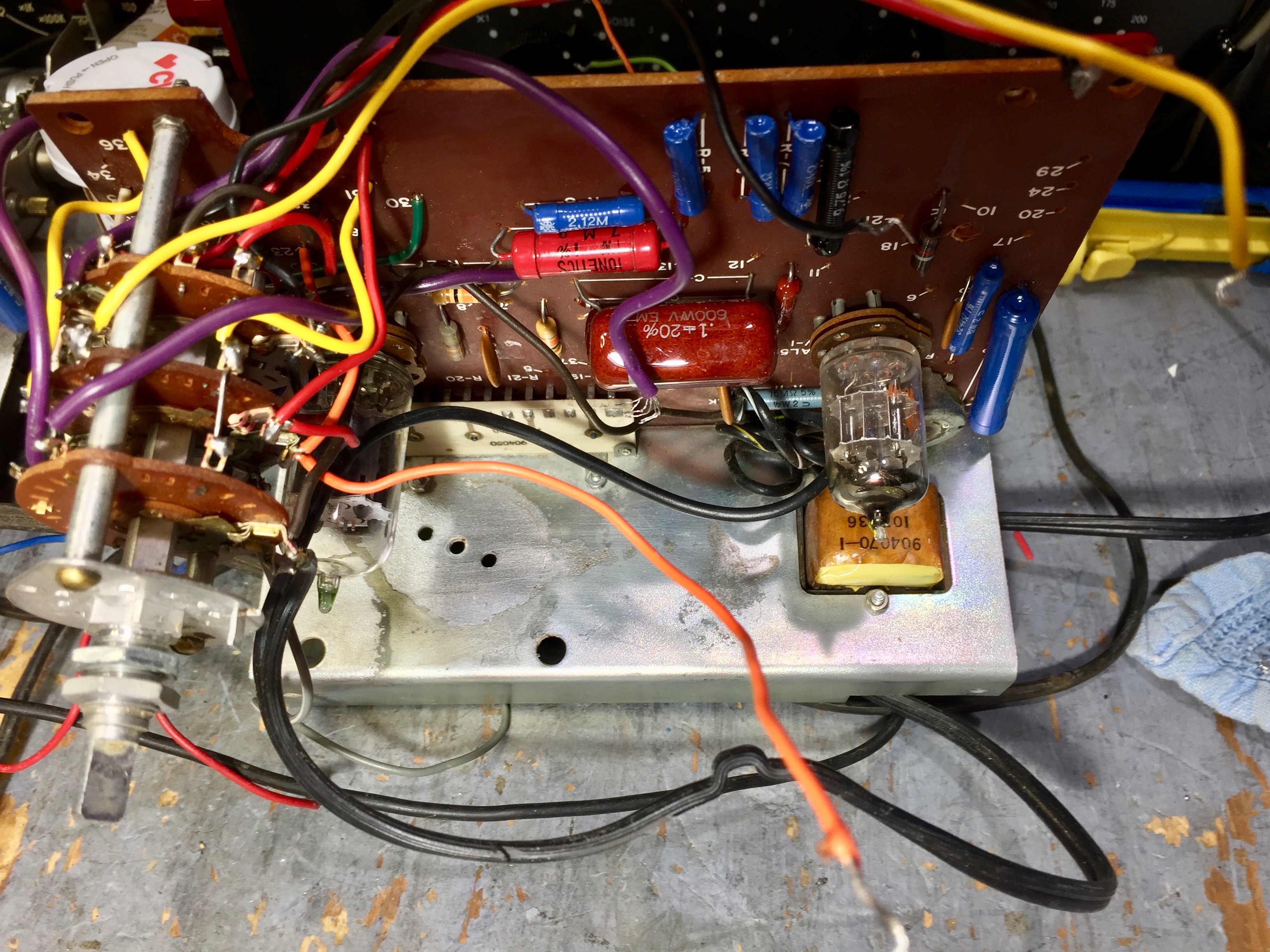
One interesting difference between the earlier production runs, K114 and K117, and the later run, L60, is in the connection of the ground clip lead. In the photo above of the L60, the ground clip lead is soldered to the ground connection from the function switch at the ground lug on the Amphenol connector.

Whereas on the K114 and K117 runs, the ground clip lead is soldered to the ground connection on the function switch at the lug on the switch.
Update:
I started reversing the steps in the WV-98C kit assembly instructions. I started at Section C, “Assembly of Range Switch, S-2”, step 50 and worked backward.

I had been looking at the unit from run K114 as I planned out removing the range switch.

However, about half-way through disconnecting the range switch wiring, I noticed that the range switch mounting nuts on the run K117 unit had been soldered to the mounting screw. Oops.

The mounting nuts on the run L60 unit are also soldered.

Fortunately after removing as much solder as I could with my trusty Soldapult solder-sucker ...

… I was able to remove the nuts and washers.

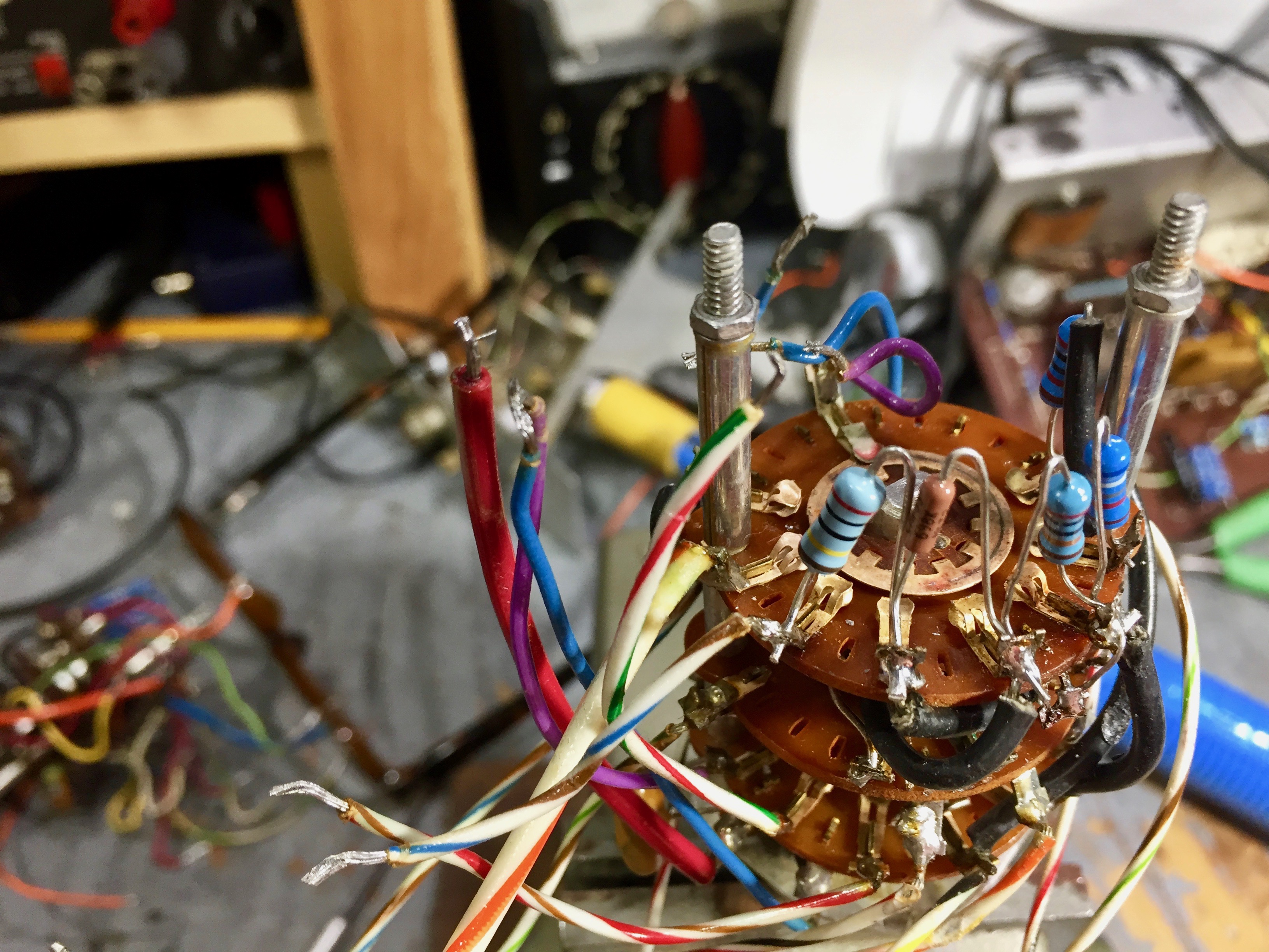
This is the run K114 unit. The wire colors don’t match those in the kit assembly manual. I took notes of the actual wire colors as I worked backward through the assembly instructions.

Here’s the K114 range switch.

It’s be much easier to replace the range resistors now.

It’ll be a little easier to work on the PCB, too, with the range switch out of the way.

This is the run K117 PCB …

… and the K117 range switch. The K117 wire colors also don’t match the kit assembly instructions nor do they match run K114.
Here’s the run L60 PCB ...

… and range switch. Again, the wire colors match neither the kit assembly instructions nor any of the earlier production runs.

I’ll need to refer to this spreadsheet when I reassemble the range switches.
Update #2
I’ve completed measuring the resistances in the three VTVMs. Click the image to get a readable version of the table.


The precision carbon film resistors in the older units, runs K114 and K117, have aged very poorly. Most are out of tolerance. The resistors in the newer run L60 unit have faired better, but some of the higher values are out of tolerance.
Does anyone know who made these precision resistors? I don’t recognize the logo, nor the initials RC.

The 5% carbon film resistors have held up remarkably well, much better than the precision 1% carbon film resistors, in all the production runs in my sample. Most are still well within spec, except for the highest value, R11, 16 MΩ. It’s typical for higher valued resistors to have more drift over time.
The carbon composition resistors in runs K114 and K117 have aged surprisingly well, with the exception of R30. The schematic shows R30 as 1/4 Watt while the parts list says 1/2 Watt. I haven’t checked what is actually installed. Perhaps it is undersized for the power dissipated in it. The newer run L60 has much more drift in the high values, R25, 3.3 MΩ, and R26, 6.8 MΩ. I guess they used cheaper resistors in the newer run.
Don’t believe the values for the 91 MΩ carbon composition resistors, R10. I can’t accurately measure resistances that high.
Update #3
On the Antique Radio Forum, Retired Radio Man asked if I had checked the linearity of the meters before embarking on the restoration. I hadn’t, but fortunately hadn’t started replacing the bad resistors. It would have been disappointing to put all that work into a unit only to find that the meter movement was kaput. So, I went about checking out the meter movements.
My first task was to zero the movements.

RCA didn’t provide a zero-adjustment screw for the WV-98 meters. Instead they provided a small hole in the front panel, covered by a plug, that provides access to the zero adjustment tang on the meter movement.

You have to use a small tool such as a tiny screwdriver to reach in and nudge the adjustment tang. You also have to be very careful to not put the tool in too deep, as that could damage the meter armature.

As a final obstacle, the meters came from RCA with a piece of cellophane tape covering the hole in the meter bezel that gives access to the adjustment tang. You can try puncturing the tape, but if you do you run the risk of the tool going too deep and damaging the movement.
The tape had been removed from one of my meters, so that was easy to zero. On the other two, I had to remove the meter from the VTVM front panel. Then I discovered the first meter was out of balance, so I had to remove it from its front panel as well.

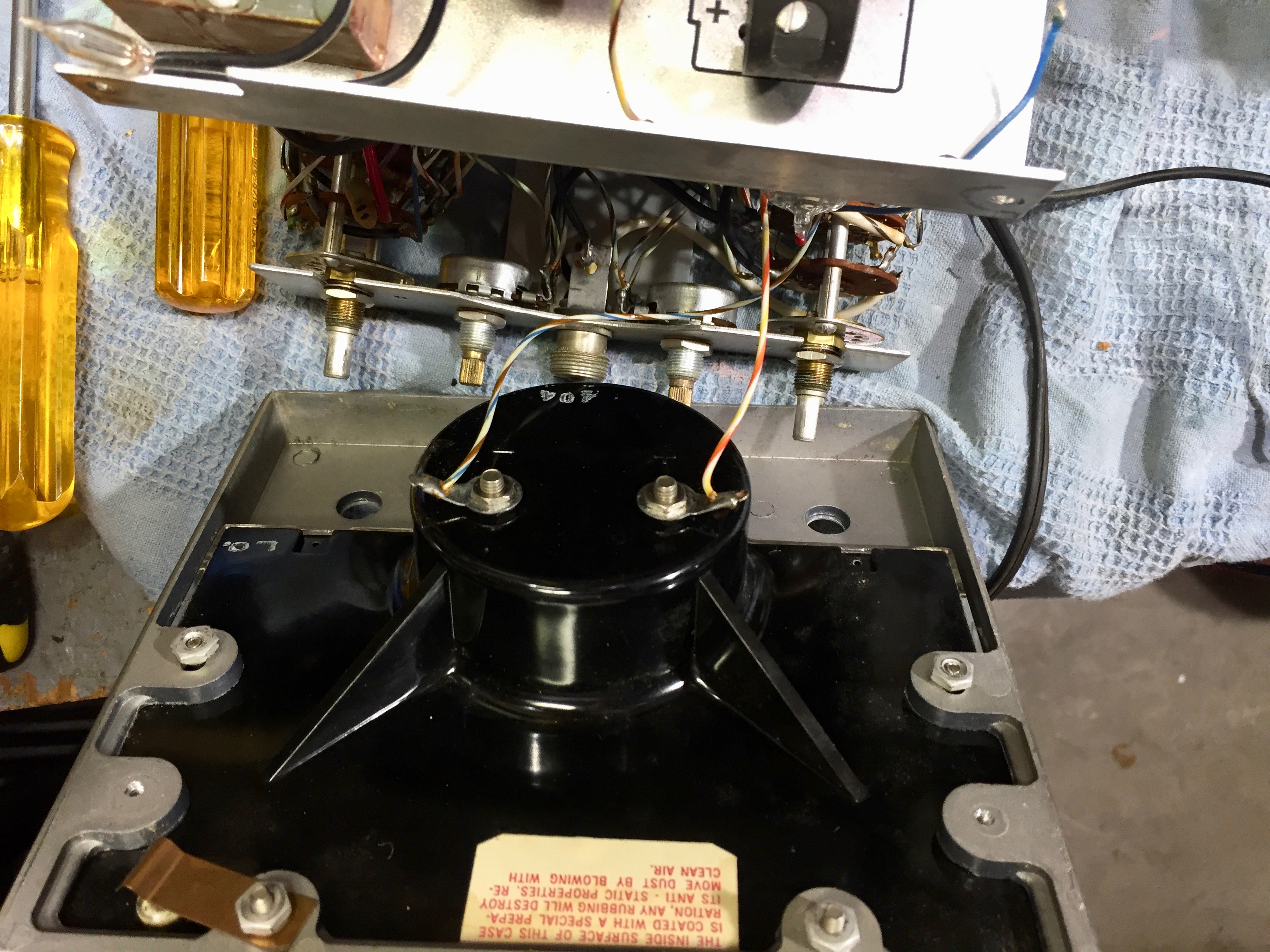
To remove the meter from the front panel, remove these four nuts and lockwashers. (The other two screws held the upper support bracket to the front panel.)

Then push the top of the meter out from the front panel. The clearance is tight on the two lower screws, but with a bit of jiggling they will come free.

I carefully removed the meter cover to get access to the weights to rebalance the meter. To remove the cover, carefully release the two tabs at the top. These tabs fit into two recesses at the top of the meter housing. You can use a 3/16” bladed screwdriver to gently pry the top of the cover away from the meter case to release a tab.

I now had access to the quad. The quad is the cross-shaped piece mounted to the meter pivot. The needle attaches to one arm of the quad. In the photo you can just see the tail weight on the arm of the quad opposite the needle. It’s the helical spring just above the solder joint for one end of the armature winding.
The balancing process is described well in several posts on the Antique Radio Forum, so I’ll just provide links to them instead of repeating the process here:
- Re: Panel Meter Restoration/Rebuild
- Fixing a Meter with a Mangled Needle - A Step By Step Guide
- Re: Triplett 60 type 2 questions
- Eico 249 VTVM, Erratic Meter
- Re: Triplett 630 meter movement
The next step was to check the linearity of the movements, using my HP 6920B meter calibrator. I collected data on the current at each cardinal point on the meter scale. I started the run at zero and increased the current to reach each point, up to full-scale. The error is calculated as a percentage of the measured full-scale for that particular meter.

The error of the meter from the K114 run (red plot) was a bit high on the upper half of the scale, although the total variation is within ±1%. The meter from the L60 run (yellow plot) looks better. But when I ran the meter from the K117 run (blue plot), the error was very high at mid-point, and the meter seemed sluggish getting past the half-way mark. I ran a curve starting from full scale and going back down to zero, to see if there was a lot of hysteresis (green plot). Some hysteresis is evident, but it’s not very bad.

I suspected there was some foreign matter interfering with the movement of the armature, so I removed the meter card and went fishing with a sliver of Scotch tape in the gap. I didn’t find anything. so my next guess was some slight corrosion of the meter pivot. This VTVM showed evidence of battery leakage at some point in its life.

I remembered a post by Chris H over on the Antique Radio Forum. He had suggested exercising a meter with a function generator to clear up minor corrosion in the bearings.
I set my B&K function generator to produce a 0.125 Hz triangle wave with a DC offset so the waveform went between zero and about 2 Volts. I connected each of the three meters to the function generator output through a 10K Ω resistor, giving a full scale of about 200 µA at the peak of the triangle wave.
I exercised the meters for a few hours one evening. Afterward, the problematic meter ran smoothly through mid-scale.
I then took a series of measurements on each meter, both running up the scale and running back down. Again, the error is calculated as a percentage of the measured full-scale for that individual meter. I took four sets of measurements in each direction for the run K114 and run L60 meters, and two sets of measurements in each direction for the run K117 meter. I plotted the average of these sets of measurements, along with the initial, pre-exercise, measurements.

This is the plot for the run K114 meter. Comparing the linearity of the initial (red plot) and final (blue plot), you can see a small improvement. The hysteresis looks pretty bad though, nearly a half of a percent in the worst case. This is why you should gently tap a meter with your forefinger before taking a reading.

Here is the plot for the run K117 meter. Exercising it with the function generator greatly reduced the sticking at the half-scale mark. The overall linearity is now pretty good.

This is the plot for the run L60 meter. The initial (red plot) and final (blue plot) have about the same total error (about 1.2%), but the post-exercise error is shifted up. There is also quite a bit of hysteresis evident.
L60 is a fairly late run, with the new-style RCA logo and the new blue paint scheme in place of the old gray hammertone. I suspect the meters in these later runs are a bit crappier as a result of cost-reduction.
Now that the meters checked out as usable, ...

… the next step was to proceed with replacing the out-of-spec resistors. Here I’ve completed reworking the range switch for the unit from run K114.

And here is the completed PCB for the unit from run K114.

The “before” photo for the K117 run.

All of the DC range resistors had to be replaced.
Another view of the K117 run range switch with new resistors.

And here’s the K117 run PCB. Sorry it’s out of focus.

Here’s the range switch from the run L60 unit. Only a few of the resistors needed to be replaced.

The run L60 PCB with its replacement resistors.

I reworked the power supplies by replacing the original electrolytic with a modern radial-leaded part, and the rectifier by a 1N4006.

I’ve reinstalled the range switch and am about to reconnect all the wires to the PCB.

Reconnecting the range switch wasn’t too bad. I just followed the kit instructions. It was very helpful to have recorded the wire colors for each step, back when I disassembled it.
I’m undecided whether I’ll complete the L60 unit before moving on to the others, or do it assembly-line style and reinstall the range switches in the other units before reconnecting the controls and connector on the lower support bracket.
Update #4
I decided to complete the run L60 unit first.

I started by reconnecting the front panel Zero and Ohms controls. I made good use of the photos I had taken during disassembly. The photos combined with RCA’s use of color-coded wires made the job pretty easy.

The next step was to reinstall and reconnect the Amphenol 75-PC1M chassis connector for the probe, and re-mount the lower support bracket. The kit instructions were somewhat helpful, although I was doing some steps out of sequence.

I still have to construct and install a battery eliminator for the ohmmeter circuit. Unlike the Heathkit VTVMs, the RCA WV-98’s use a floating battery. Neither side of the battery is connected to the chassis.

My design for the Heathkit IM-13 battery eliminator assumes the negative end of the battery is grounded to the chassis, and the PC layout achieves this through one of the mounting stand-offs. I’ll either have to design a new PCB for the RCA WV-98’s or hack up a mounting method that leaves the negative rail of the supply ungrounded.

It looks like a VTVM again! And an initial checkout and preliminary calibration shows it to be working, with the exception of the ohmmeter portion due to the lack of a power supply.
One common issue with VTVMs is that the 12AU7A initially has a high grid current. This shows up as the zero drifting up as you switch to the lower voltage ranges. When I first turned it on, when I zeroed the meter on the 50 volt DC range, the needle would drift up to the “5” mark on the 0-50 DC scale when switched to the 1.5 volt range. That’s about 10% of full scale.
The high grid current is due to gas in the tube, leaking in over all the years it sat abandoned and not in use. After leaving the VTVM powered-on for three days, the getter scavenged much of the gas from the tube and the zero drift on the 1.5 volt range went down to about 1/2 of a division on the 0-50 DC scale, which is about 1% of full scale.
Note that the zero drift is much larger on the 0.5 Volt DC range. The RCA manual instructs you to re-zero the meter when switching to the 0.5 V DC range.
Now that it has aged a bit, I can start to do the final recalibration. I’ll ponder the battery eliminator question for a while, and leave deciding on an approach until after I’ve reassembled the other two meters.
Update #5
I’ve completed calibrating the run L60 unit, except for the resistance ranges.

Click the above thumbnail for a readable image. The VTVM easily beats its accuracy specification.
Update #6
I’ve completed the run K114 and run K117 units, except for calibration, and added battery eliminators to all of the VTVMs.

Here’s the run K114 unit with the range and function switches re-installed on the PCB.


Reconnecting everything was a bit tedious.

Here is the run K117 unit.


On the run K114 unit, I lost the Heyco clip for the line cord. I tried all the different sizes of the Philmore brand Heyco clips carried by my local electronics parts emporium, Electronics Plus, but none of them would fit.

I cons’d up a replacement using a cut-down Waldom vinyl grommet ...

… and an Underwriter’s knot for strain-relief on the line cord.

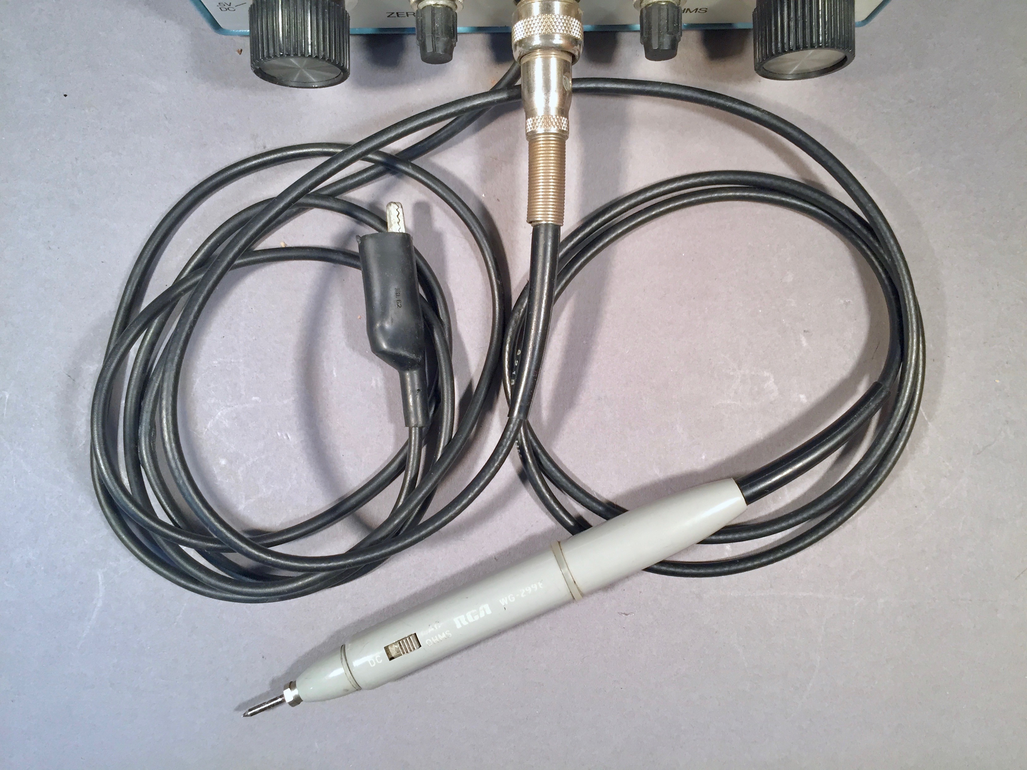
I also made up a home-brew replacement for the original RCA WG-299D probe for the run K117 unit. I prefer to keep the original Amphenol 75-MC1 connectors, rather than replacing them with BNCs.

Here I’ve mounted my transformer-powered VTVM battery eliminator circuit in the run K117 unit.

I mounted it using #6 x 3/8 round-head nylon screws and nuts. I used nylon because the board was laid-out assuming the ground bus would be grounded to the chassis through one of the mounting standoffs. However, the WV-98A/B/C VTVMs require a floating voltage source for the resistance range, so I have to isolate the PCB from the chassis ground.

I used a stack of two #6 nylon washers as spacers to raise the PCB above the chassis. Note the chassis mounting hole next to the left-hand diode. With the board oriented this way, it’s hard to get a screwdriver on the bolt that goes in that hole.

There’s no pad on the PCB for the negative connection, so I just soldered a wire to the ground bus on the back of the PCB.

I drilled a hole in the PCB to feed the line voltage to the board. I made the connections to the traces that provide power to the neon pilot lamp.

On the run K114 unit, I mounted the board rotated 180° compared to the other unit, and put the nuts on the bottom rather than the top.

This made it much easier to access the chassis mounting screw, here shown in the upper left of the photo.

Here’s the almost-finished run K117 unit. I burned-in the VTVMs, waiting for the grid current in the 12AU7A’s to drop. The run K115 unit settled in after a couple of days, but even after four days the run K117 unit still had four divisions of grid current on the 0-50 scale when switched to the 1.5 Volt range. It needs a new 12AU7A before I can calibrate it.

Note that the run K117 unit has a replacement meter and front panel from a later run, with the blue paint rather than the gray hammertone.

I guess that the old meter was damaged by battery leakage. You can see where the battery leakage damaged the paint on the case at the lower left corner in the photo above.


The previous owner (MIT’s student EE lab) has touched up the paint on the rear of the case, presumably where the battery leakage damaged it.


Here’s the complete package.


Here is the run K114 unit. Note the older style for the front panel legends, compared to the run K117 unit with the replacement new-style front panel and meter.


Finally, here are the record-shots for the run L60 unit.


I think the previous owner put the stick-on rubber feet on the bottom. The kit manual mentions applying self-adhesive strips of cork to the raised areas on the bottom of the case, but I haven’t seen any meters that show evidence of that.

Here’s the L60 unit with its WG-299E probe.


Update #8
I started calibrating the run K117 unit. It was checking within spec on DC volts until I reached the 350 Volt cardinal point, when my HP-6920B meter calibrator went into current limiting. Uh-oh, my homebrew probe was breaking down at about 300 volts. I guessed there was some flux contamination that was breaking down.
It was a good lesson for me. I should be testing these probes on my General Radio 1862-B Megohmmeter at 500 volts before gluing them up, and running a 1500 Volt breakdown test on them.

I fired up my General Radio 1862-B Megohmmeter and started testing my probes, but quickly ran into problems with the 1862-B. First, with nothing connected, the meter was reading well under 100 GΩ at 500V. I noticed some dust had collected on the binding posts and front panel, so I cleaned that up with electronics-grade isopropyl alcohol. You want to use anhydrous isopropyl for this, as the drug-store 91% has a bitterant added to prevent people from drinking it, and that often leaves a little residue that defeats the purpose of removing contaminants.
I was surprised to see how low the resistance went when the front panel and binding post were wet with isopropyl. When you’re measuring at the hundreds of megohms level, a lot of things have a little leakage resistance.
Second, after cleaning, the grid current was still too high for the highest range (100 GΩ at 500V, 10GΩ at 50V) to be usable. The manual mentions that “[g]rid current may be excessive if the instrument has not been used for some time; normal operation for ten minutes will reduce the grid current satisfactorily.” I haven’t used my 1862-B very much since I obtained it six years ago, and ten minutes wasn’t enough to bring the grid current down. I left it on overnight, and that did the trick.
Next, I cut open the probe to access the circuitry and the end of the cable. I used a razor saw to open the joint where I had glued the probe together. (I really should figure out a way to make these maintainable.) There was some flux on the proto-board, but cleaning that off wasn’t enough. I enlarged the gap between the pads where I had terminated the cable shield and the traces for the switchable resistor, and that helped considerably.
I then removed the Amphenol 75-MC1F connector from the other end of the cable. I trimmed the shield braid back a bit further from the end, and that brought the insulation resistance up to a satisfactory point.

I glued the probe back together and applied new heat-shrink tubing as a strain-relief.

The glue joint is pretty ugly but at least it works now. The insulation resistance from the connector shield ring to the probe tip is 110 GΩ. The resistance from the probe tip to the probe body is 50 GΩ. I put 1500 Volts between the connector shield ring and the probe tip and measured less than 100 pA of leakage.
I went back and checked my other home-brew probes, and fortunately they were all OK.

I’d make another probe, but I’m out of the tiny slide-switches that I use for them. I bought them as surplus from Electronics Goldmine, and they sold out their stock of them years ago.
I’ve stocked up on some C&K ET01 surface-mount toggle switches from Electronics Goldmine, but they require a larger diameter probe. Evergreen doesn’t make anything larger than 1/2” diameter tubing. I’ve ordered 3/4” ABS tubing from Plastruct. It’s more expensive than styrene, but ABS is more rugged so it’ll make a better probe.

Plastruct makes elliptical and semicircular domed ends for their tubing, so I'm going try using those for the ends for the new probe design.
Update #9
I’ve finished calibrating the run K117 unit.

It easily meets its specified accuracy.
Next up: calibrating the run K114 unit.
Update #10
I’ve finished calibrating the run K114 unit.

It meets its specs, but the 150, 500, and 1500 volt ranges were pretty close to the edge, and the AC zero and 50 volt range calibration were a little flakey. But after a couple of rounds of calibration and checking the lower ranges it seemed to settle in. I’ve put it on the bench to use as the main VTVM for a while, to see if the calibration is going to drift.
I’m reminded of the troubles that Calambres had with his RetexKit VV-1 VTVM (a Spanish clone of the Heathkit IM-11 VTVM). His upper AC ranges were also inaccurate. He solved the problem by replacing the 6AL5. I should give that a try.