

Over on the Antique Radio Forum, Williwork posted his experience restoring a Simpson model 383A Capacohmeter. It's an interesting instrument. It measures capacitance using the ohmmeter method, measures insulation resistance using 300 volts and a 87 megohm reference resistor, and measures leakage at working voltage using something Simpson calls a "pulse test".
The pulse test uses a thyratron relaxation oscillator driven from a low-current one kilovolt supply. The oscillator charges a capacitor through a high resistance. When the voltage on the cap reaches the trigger voltage on the thyratron as set by a control voltage on the grid, the thyratron breaks down and starts conducting. This then places the charged cap across the capacitor-under-test, driving it with a pulse peaking at the controlled voltage level.
I think this odd "pulse test" is just Simpson's marketing department making a virtue of a cost-cutting necessity. I suspect Simpson came up with this clever thyratron relaxation oscillator circuit to provide an inexpensive way of regulating the voltage applied to the capacitor under test, rather than pay for an electronically-regulated HV supply, an unregulated Variac-driven HV supply, or even a HV supply with enough current capacity to drive a wire-wound potentiometer voltage divider.
Williwork noticed some odd behavior when calibrating his Capacohmeter. This, plus the fact that I'd never played with a thyratron before, stimulated me to restore the one I had on my shelf.
I got the schematic and a manual from BAMA. The Simpson 260 site also has a scan of the manual, but the one on BAMA is higher-quality.

The unit was pretty clean. I chopped off the old two-wire line cord and later replaced it with a three-wire cord. I had to run the ground wire half-way across the chassis to get to a convenient screw for the ground lug.
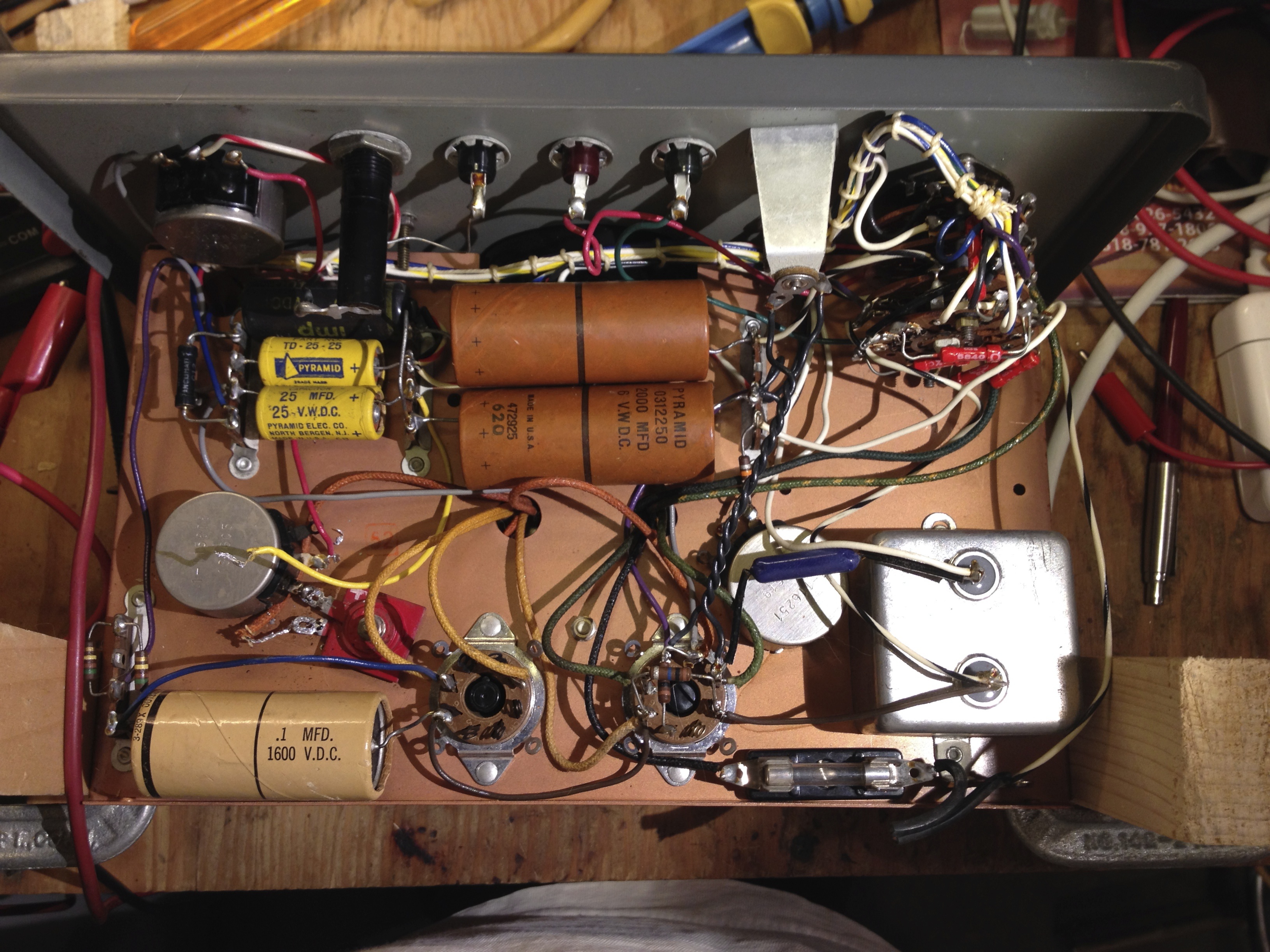
There are some high voltage capacitors in the unit that would be a bit hard to replace, like the 0.1 µF 1000 VDC cap in the lower left of this photo. I didn't have a kilovolt supply to fully test the leakage on these, but at a couple of hundred volts they don't show any leakage.
I reformed the low voltage and 300 volt electrolytic capacitors; they came up fine. Simpson used good quality components.
The resistors were all still within the specified tolerance limits.

Even the black beauty cap at the upper left of the photo showed no leakage.
I replaced the low-voltage selenium rectifier at the lower center of the photo with a 1N4003. I didn't bother with a series resistor, though I should have.

I replaced the 300 volt selenium rectifier with a 1N4007, again without a series resistor.
The unit calibrated fine for the capacitance and megohm meter functions.
I had advised Willitwork to try using a peak detector and a voltmeter to measure the peak voltage, since the repetition rate of the pulses is quite low, about 0.2 Hz when turned up to the max. of 900 volts. But when I looked to do this myself, a quick calculation convinced me that since I don't have an electrometer (with its very high input impedance) I didn't have a chance of making a peak detector that would hold a voltage long enough for me to get a good reading. So, I had to use my scope.
For the high voltage pulse test, I didn't want to trust my cheap import 100:1 scope probe, as it's only rated for 600 volts max.

So, I cons'd up a 100:1 divider using a Caddock 5 megohm 1% HV resistor that I bought as surplus, a 47.5K 1% metal film, and a Bournes 5K 10-turn trim-pot. I trimmed the pot to get exactly 50.5K ohms in the bottom arm of the voltage divider for a 99:1 ratio with the 5.00M ohm resistor.
I checked the divider using my scope's calibrator; it didn't seem to need a compensation capacitor to show a good square-wave response.

I used this divider and my scope to measure the peak voltage of the pulse test. The calibration was still spot-on.
Regardless of the merits of the pulse test, I think the megohm function of the Capacohmeter is useful enough to earn it a place on my workbench.
Update:
The pulse test showed some leakage even on a good capacitor, so my attempt to reform the 2000 µF 6 wvdc electrolytic capacitors didn't pan out.

I replaced them with modern 2200 µF 10 volt capacitors. Compare the size of the new ones to the old capacitors shown in the earlier photos above.

I didn't have any 22 µF 25 v capacitors on hand, so I left the originals in the firing circuit for the thyratron. I did, as a precaution, replace the Black Beauty filter capacitor on the low-current 300 VDC supply for the megger function. However, once replaced, I couldn't zero the resistance scale! While trying to diagnose the problem, I discovered that putting the 10 megohm input resistance of my Fluke 27/FM meter across the 300 volt supply allowed me to properly zero the scale. Apparently Simpson designed-in the leakage of the Black Beauty paper cap! So, I added a 10 MΩ resistor across the new polyester film filter cap to simulate the leakage of the old capacitor.
Measuring it out of circuit, the Black Beauty only showed 0.4 µA of leakage at 300 volts. That's about 7.5 MΩ.

The cap is actually a Pyramid "IMP" rather than a real Sprague Black Beauty, which someone on the internet claims is a di-film (mylar and paper) capacitor. If that's correct, I'm surprised that the leakage is that high.
Pulse mode experiments
Willitwork over on the Antique Radio Forum had been trying to calibrate his 383A using a method I suggested - a peak detector consisting of a diode, a capacitor, and a DMM. (At the time I suggested this, I didn't know that the 383A has such a low pulse rate at high voltage; the time constant of a reasonably-sized cap with the 10 MΩ input impedance of the DMM is just too short for this method to be effective.) He reported some surprising results - large loud sparks and a blown-up DMM :-(
Later, I read this caution on page 34 of the manual: "Do not apply the Capacohmeter leads across a transformer winding, inductance, or rectifier circuit. The output from the instrument can produce undesirable results for such connections." The caution about inductances I can understand, but I don't get the caution about rectifiers.
I wanted to understand what was going on, as I couldn't see anything in the circuit that would multiply the 383A pulse output voltage to the point where a spark would jump a large gap. But I also didn't want to blow up my meters or scope. My homebrew high voltage 100:1 divider provided the solution. In the meantime I had also obtained an HP 1741A storage scope, which is perfect for examining a low-repetition-rate fast pulse signal.

I wired the divider across 0.1 µF 2 KV ceramic cap, and a 1N4007 diode in series with them.

The divider feeds channel 1 of the HP 1741A scope.

I started by shorting the 383A output and zeroing the meter on the megohms function. This adjusts the internal voltages to compensate for variations in the power line voltage.

Next, I connected the 383A across the capacitor and paralleled divider. The megohmmeter properly reads 5.05 megohms.

Setting the 383A to 500 volts "PULSE", the meter shows the cap to be OK. I guess 5 megohms leakage isn't very much, and the leakage is symmetrical, so it balances out of the pulse test circuit.

Here's the pulse waveform, at 100 volts/division vertical and 1 ms/division horizontal. The 5.05 MΩ impedance of the divider knocks the peak pulse voltage down to 450 volts. When I measure it with a 10 M 100x scope probe, it's spot-on at 500 volts. You can't see it at this scale, but speeding up the horizontal sweep reveals a very small ripple at about 100 kHz on the decay. I suppose it's the result of a parasitic inductance resonating with the capacitor under test.
There's also some 60 Hz ripple from the odd circuit return connection to the thyratron filament supply rather than to ground. Maybe that's to synchronize the firing of the thyratron to the 60 Hz power line frequency, so that old service grade scopes could use a line-triggered sweep when calibrating the pulse voltage?

Now for the moment of truth. I connected the 383A to a diode and turned on the pulse.

This time, the asymmetrical leakage due to the diode shows up as a "bad" capacitor.

At the same 100 volts/division vertical and 1 ms/division horizontal settings, you can see the peak capacitor voltage is still 450 volts, but the decay is much longer due to the diode isolating the capacitor from the 383A discharge path.
No fireworks, but I didn't turn it up to the full 900 volts. Still, I don't see anything that would lead me to think there would be any problem at 900 volts.
Maybe I should try the experiment with the diode reversed - I wonder which way Williwork had his connected? Update: he says his was connected the same way, near as he can tell after the fact.
Update: another Simpson 383A thread showed up on the Antique Radio Forum. The fellow was going to replace the 0.1 µF 1600V capacitor as a precaution. This prompted me to check the leakage on the HV caps in my 383A, now that I have a high voltage supply.

At 1600 volts, C3, the 0.1 µF 1600V cap, was leaking 0.86 µA. That seems fine. I figure it only sees about 1200 volts at most in the circuit.

I guess it's a paper in oil capacitor. It's in a metal case with what look like plastic end-pieces, covered with a cardboard wrapping. Made by Sprague, has "3-289X" printed on it.

To test C5, the 1 µF 1000V cap, I had to unsolder one side to isolate it. At 1000 volts, it's leaking 12.1 nA (0.0121 µA). It looks like a paper in oil cap, but it's in fine shape.
While I had it open, I also replaced the two 25 µF 25 volt capacitors with modern 22 µF 25 volt axial electrolytics. I measured the leakage on the Pyramid caps I removed, and the leakage at 25 volts was less than my Fluke 27/FM can measure, so it's something less than 100 nA.