

I started work on restoring my V-M 1465-2 AM-FM Stereo tuner while waiting for parts to complete my V-M 307 restoration.

The bezel got a bit banged-up on the move from my parent's home in Towson, Maryland.

I first pulled all the tubes and cleaned the crud off the chassis with isopropyl alcohol and a toothbrush.

A look at the chassis shows that Voice of Music used pretty high-quality components for the early 1960's: carbon film resistors, polystyrene capacitors, and ceramic disks. There were a couple of paper bypass caps.

Is this a film cap or a paper cap? I'll have to test it and see if it leaks, then dissect it.

The blue electrolytic looks to be well sealed. I wonder if it is still good? (Update: it's working fine. It's made by Ducati, in Italy. Still, I'll replace it as a precaution.)

I do need to re-stuff the main electrolytic can.

I used a couple of short pieces of 1x2 and some small C-clamps to improvise a chassis stand.

Getting the can electrolytic out was a bear. One of the tabs was soldered to the steel chassis and I simply could not get things hot ehough to suck out all the solder. I ended up breaking off that tab.

I restuffed it using 12 mm diameter radial electrolytics from Mouser.

I replaced the paper bypass caps with modern film caps.

I needed to get out my Weller 8200 soldering gun to work on the soldered connections to the steel chassis. I also tried a modern Weller D550 with the set-screws rather than tip-nuts, but my old 8200 seemed to deliver more heat. Too bad Apex or Cooper ruined a good product by cheapening the design.

I'll have to leave the one electrolytic bypass cap in for now, until my next Mouser order.
Update:
I cleaned the tube sockets and pins, applied some DeOxIt to the tube pins and the socket fingers, left it alone for a while, then cleaned up the residue and plugged in the tubes. The tuner mostly works fine and is much more sensitive than my Technics SA-200 shop receiver. It still had one problem that I remember it had back in the early 1970's - the stereo indicator light didn't work.
I had a poor copy of the schematic from the owner's manual (which I seem to have misplaced; I can't find it now that I need it), and so I was able to track down the fault.

This coil (L6 on the schematic) is part of a 19 kHz L/C filter that amplifies the pilot tone and applies it to a neon lamp which is the stereo indicator light. It had gone open. Fortunately it failed at one of the ends and I was able to splice in a small section of 30 gauge wire-wrap wire to fix it. Yay!
One of the #1847 pilot lamps failed while I was troubleshooting the stereo indicator problem, so now I need to order some replacement lamps.
My parts order from Mouser arrived, so now I can replace the blue Ducati-made electrolytic.
Next up: restoring a VHF-capable signal generator so I can align the tuner.
Cabinet restoration

As I mentioned at the beginning, the front panel was dented in the upper left ...

... and the bezel was dented in the upper right.
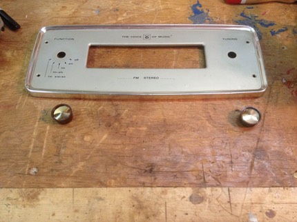
I was successful in removing the dent in the upper left, but less so with fixing the dented bezel. I cleaned up the front panel and the knobs with Gojo, as well as the rest of the cabinet.

Here's some photos of the finished product.

