

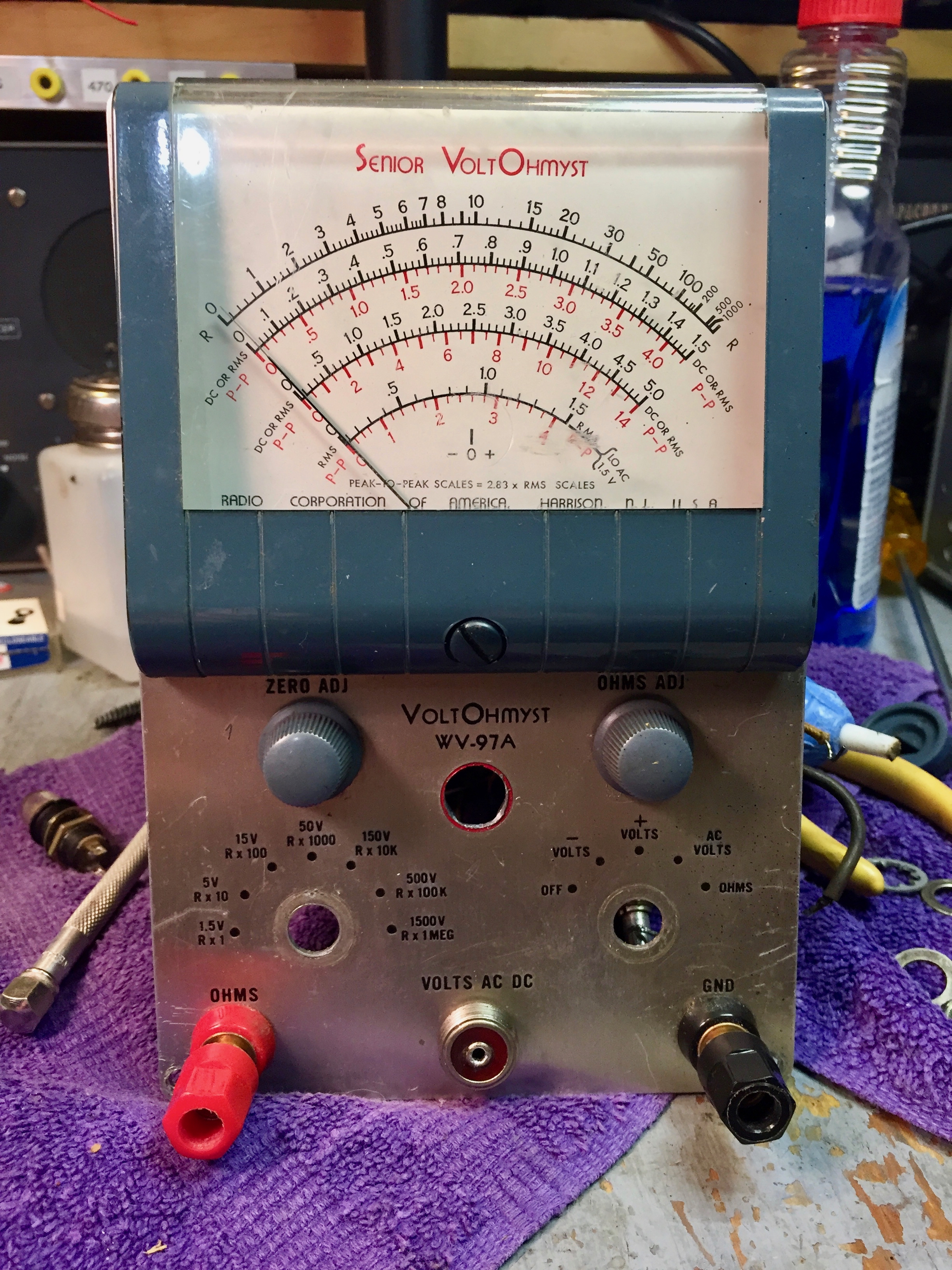
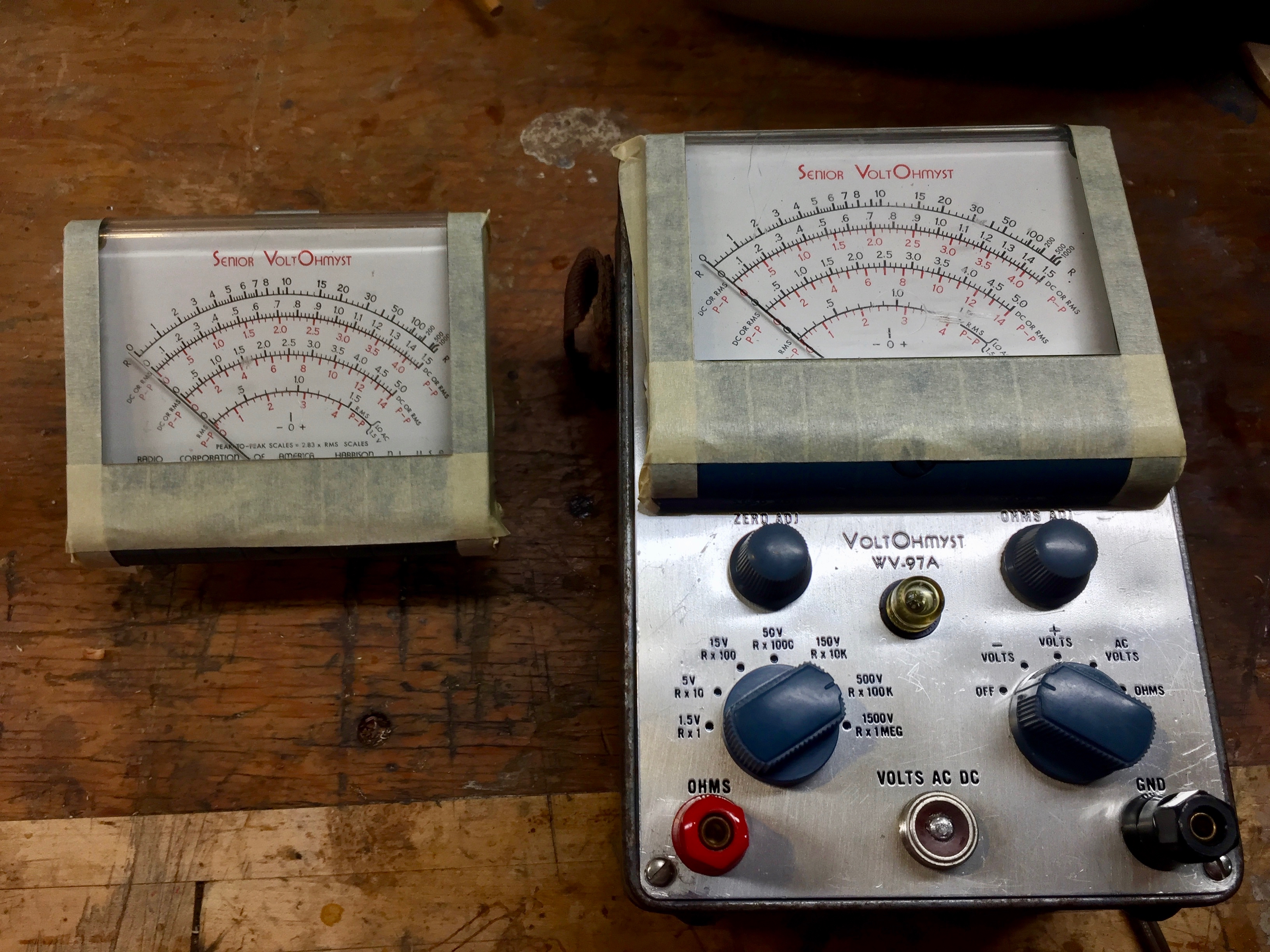
I promised ARFer John Stouffer a VTVM from my stash. I had also promised ARFer Hylaphone that I'd find good homes for a batch of three RCA WV-97A Senior VoltOhmysts that he had given to me, so one will be on its way to John. But first I have to restore it.
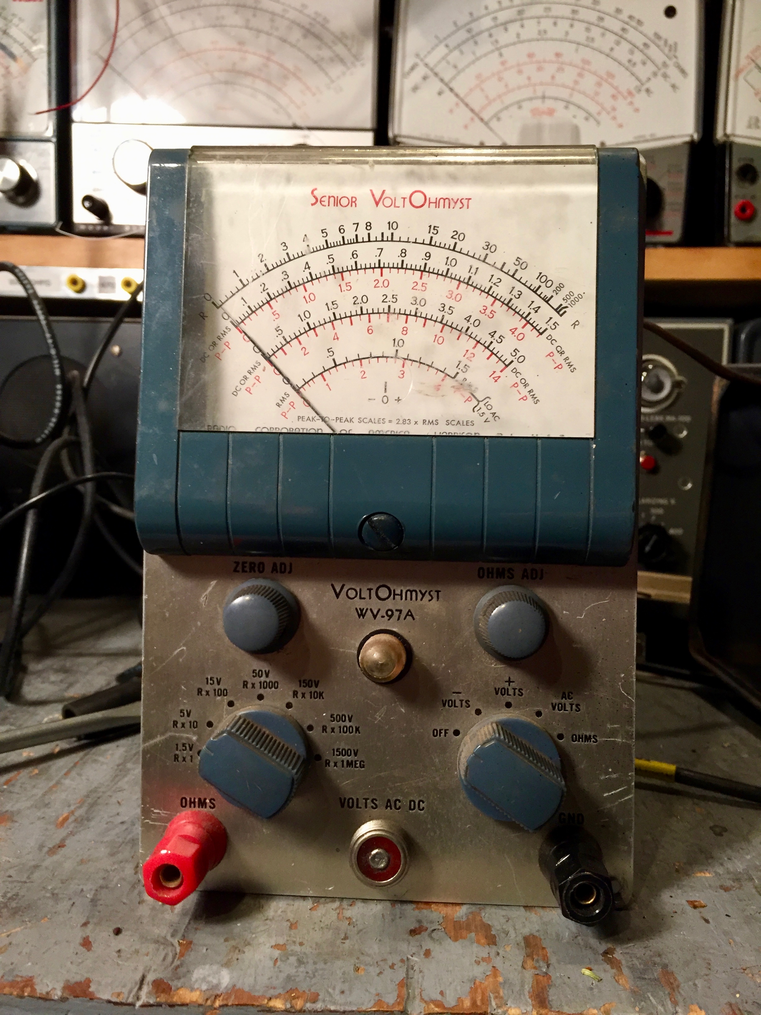
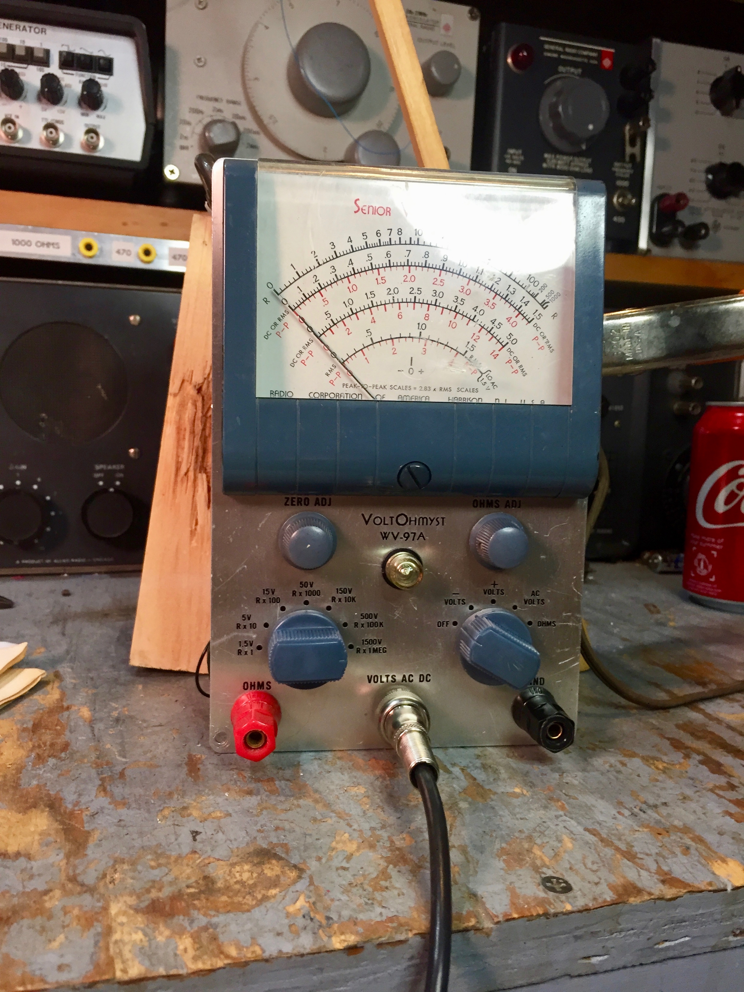
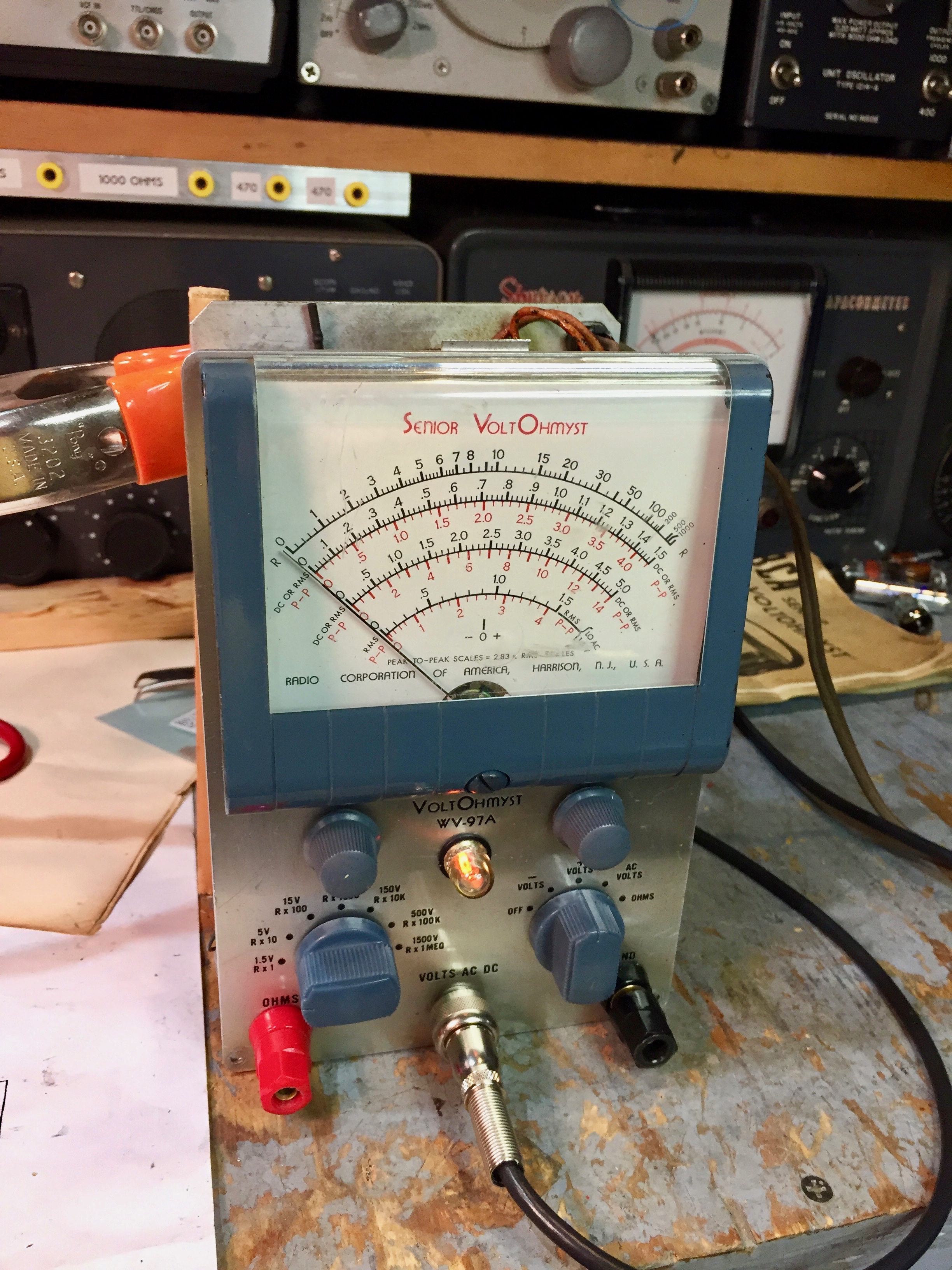
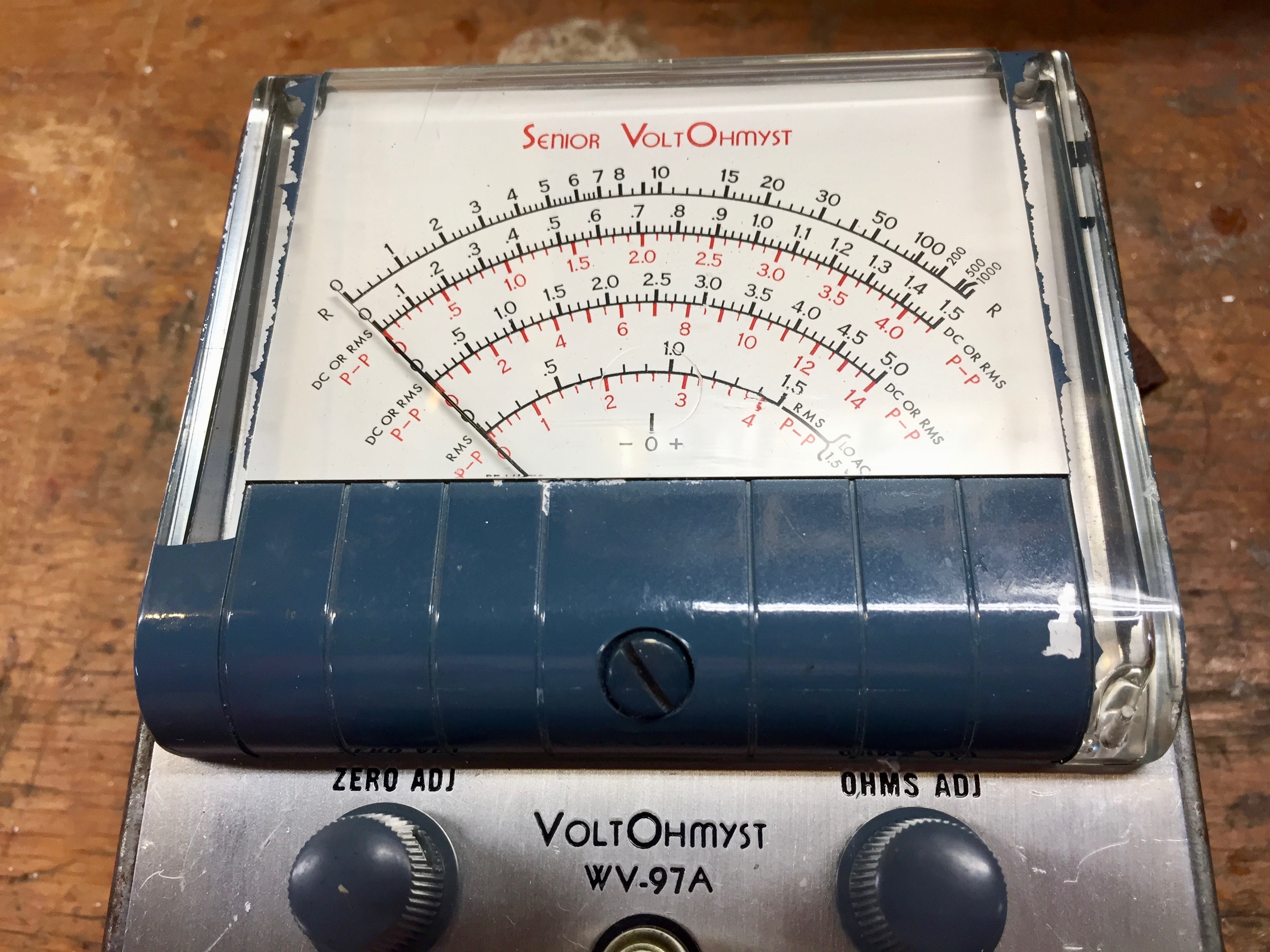
These VTVMs are very interesting. They apparently came from some service shop, and had been repaired and modified. On two of them, including John’s, the RCA meatball logo had been neatly punched out and replaced by a pilot light.
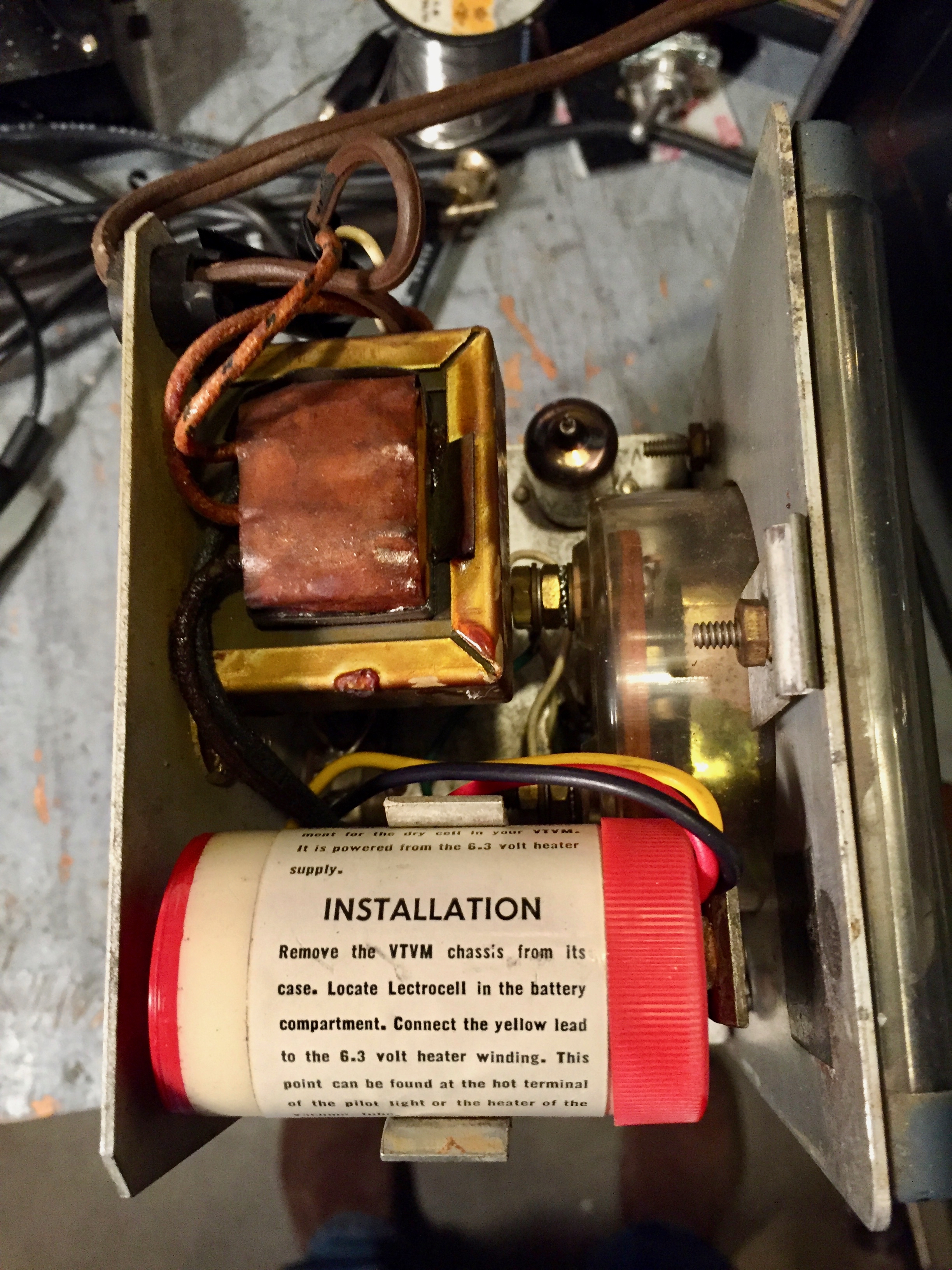
All three had Lectrocell battery eliminators installed in them.
I’ll write a separate post about the Lectrocell.
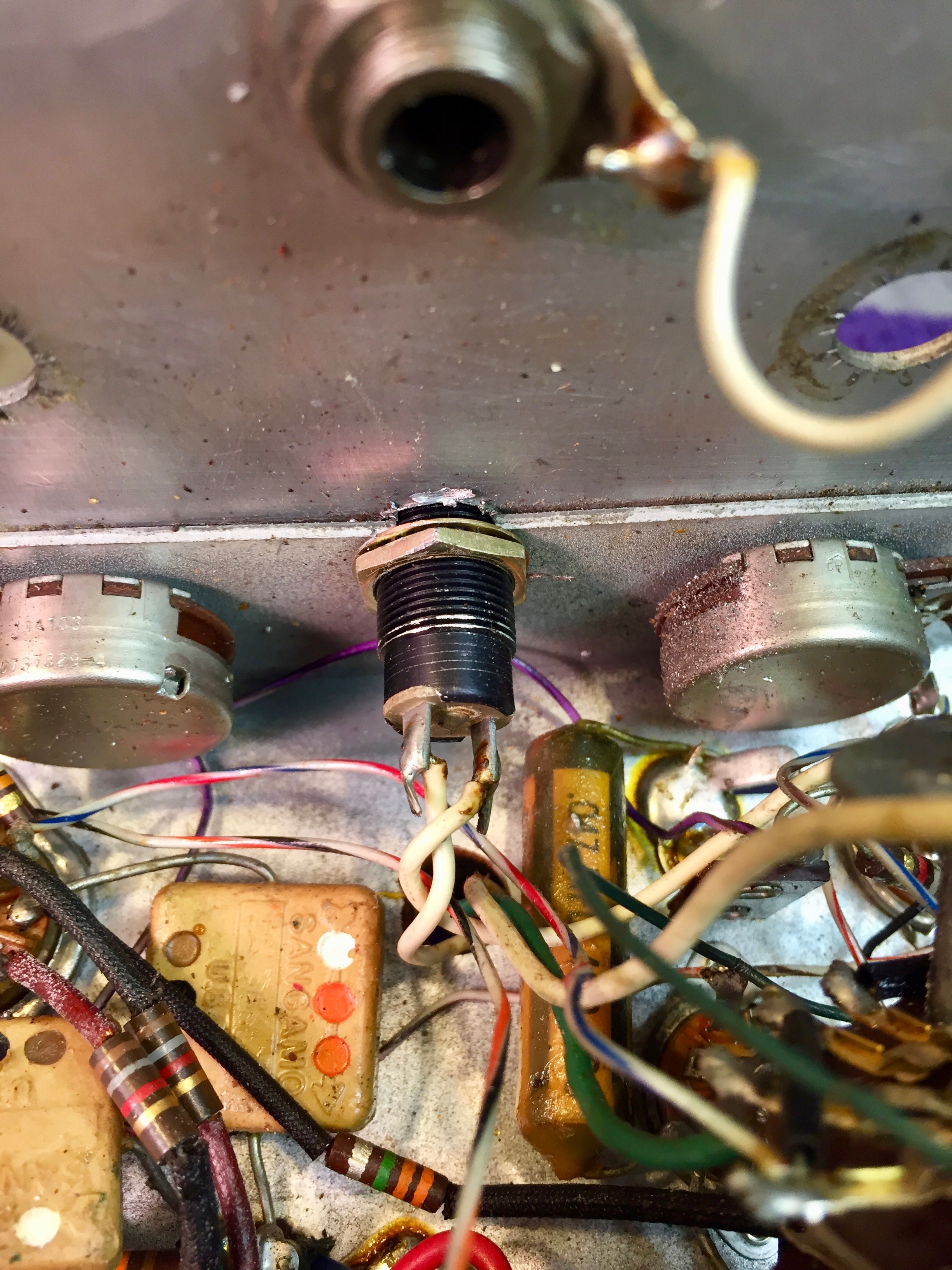
The original banana jacks were replaced by binding posts.
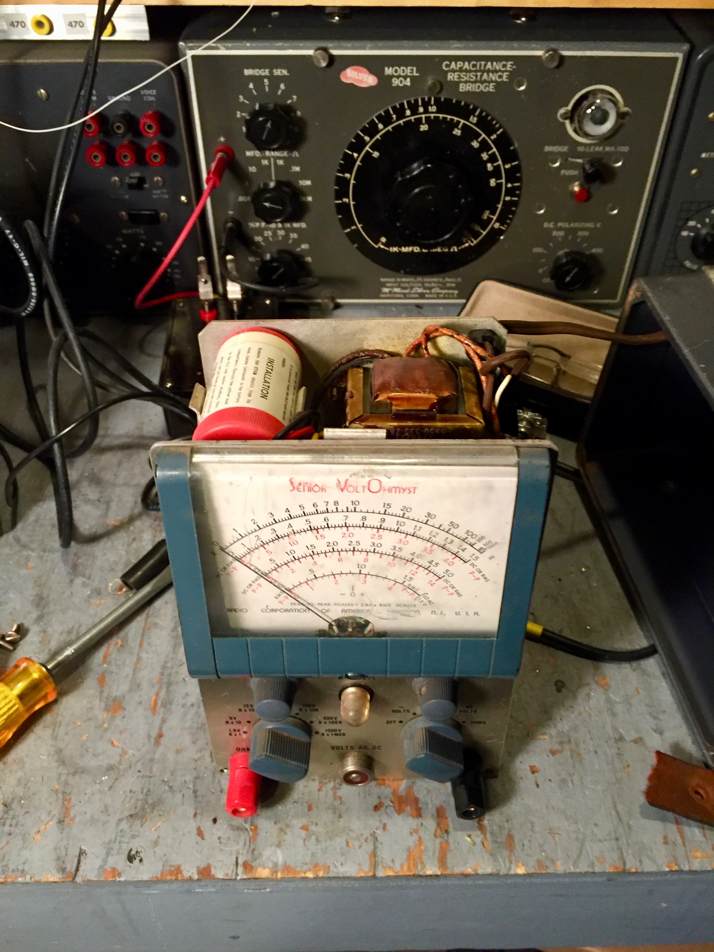
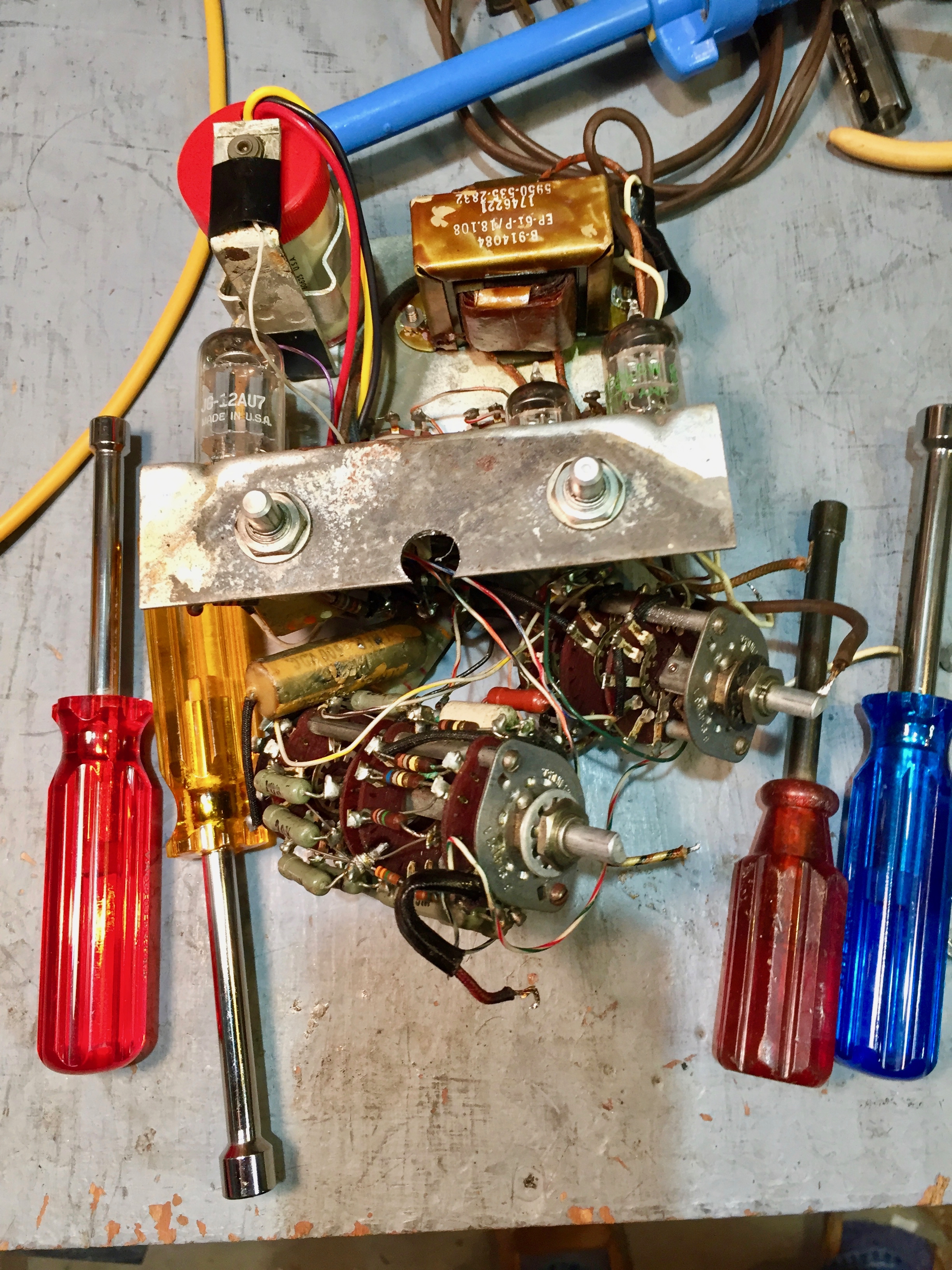
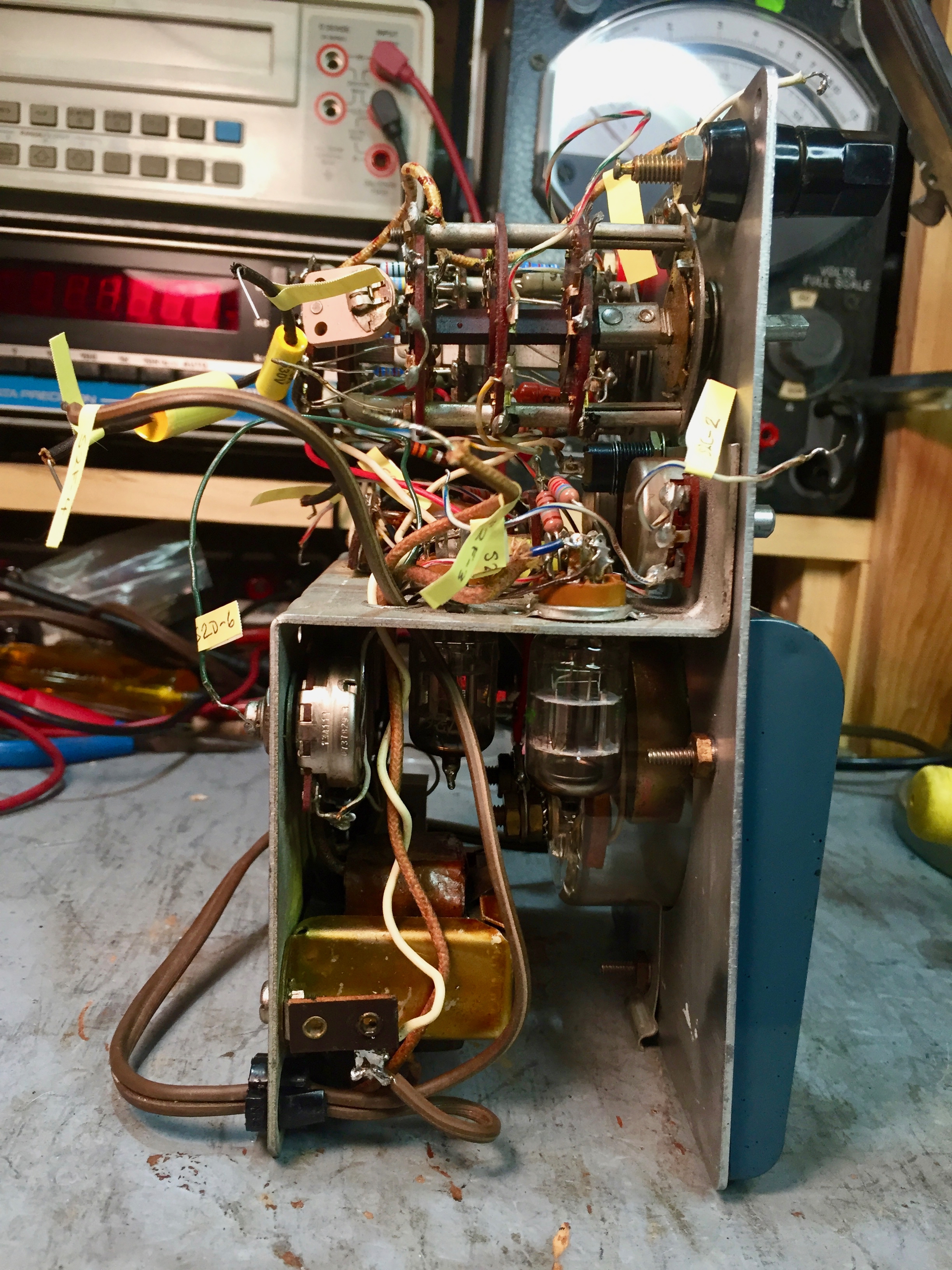
You have to remove range and function switches from the front panel to gain access to the components.
I took lots of photos so I can get everything back together in the right place.
I have to admit to feeling some trepidation, though, every time I start dismantling a piece of gear.

Will I be able to get all those wires back in the right place?
Or will I spend hours tracing the schematic, trying to find a mis-wire?
The pilot light has to be disconnected and removed from the front.
Next step is to remove the Zero Adjust and Ohms Adjust knobs and the control nuts.
At first I thought the chassis was spot-welded to the front panel ...
… because the corrosion from a leaky battery had glued them together.
But a little persuasion got the chassis free.
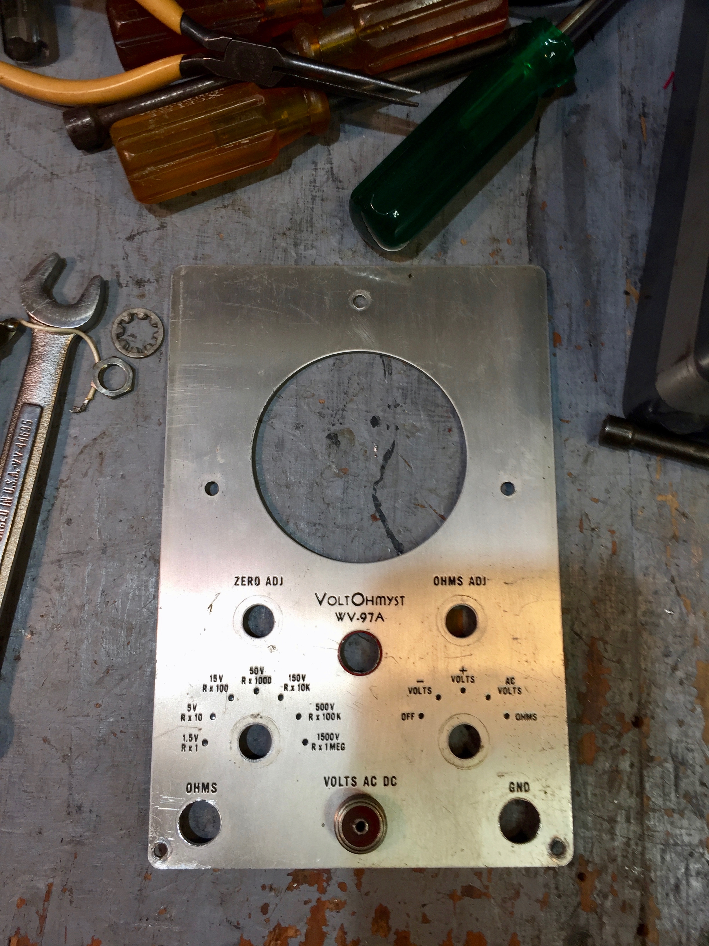
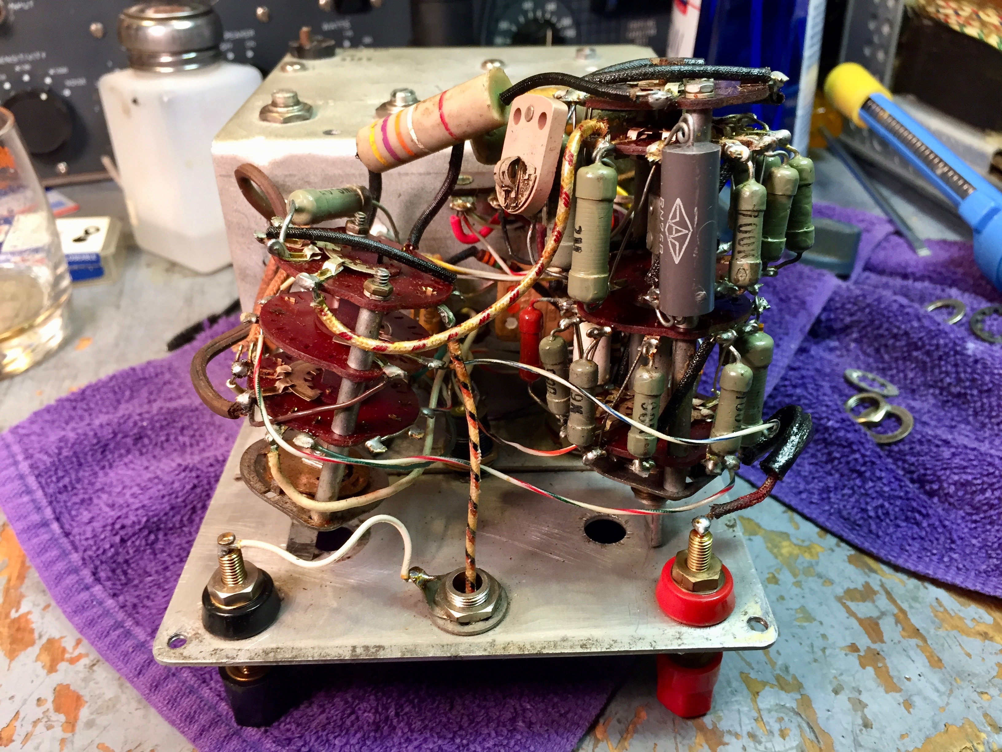
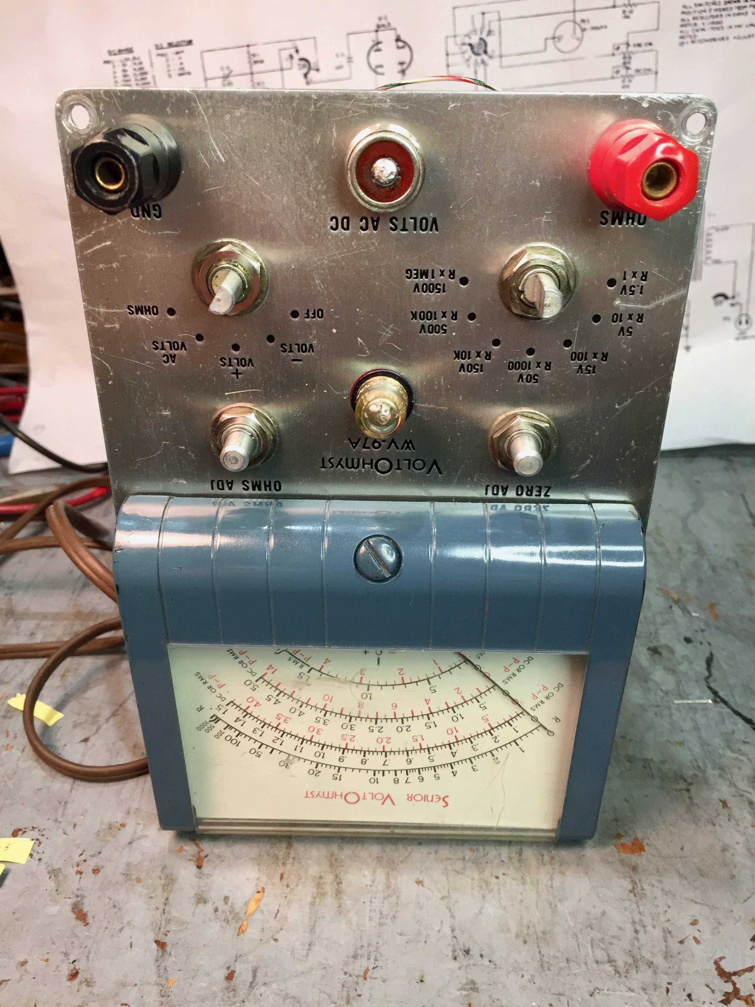
The holes for the Ohms and Gnd connectors have been enlarged to accommodate the binding posts, so there’s no going back to the original banana jacks.
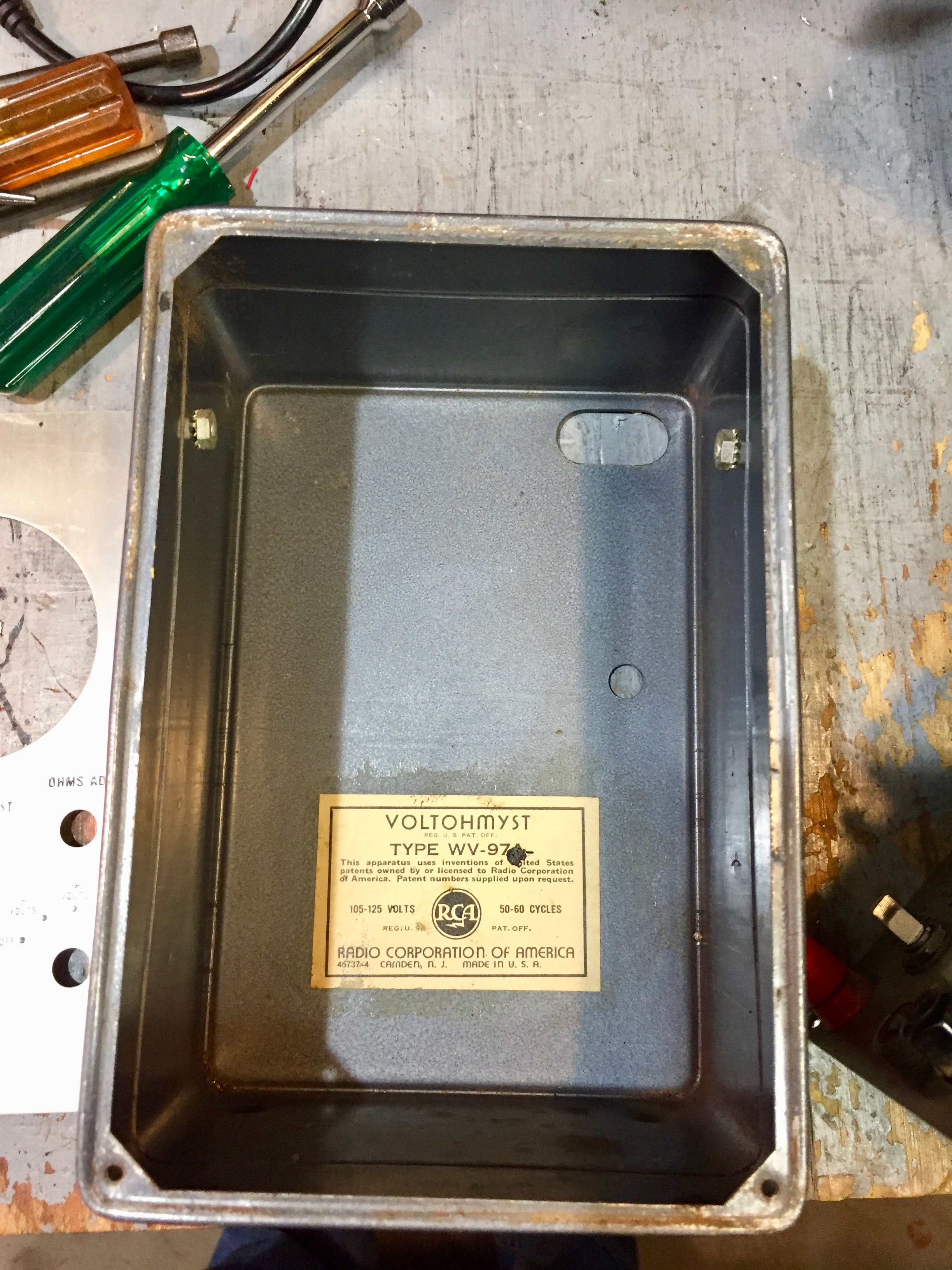
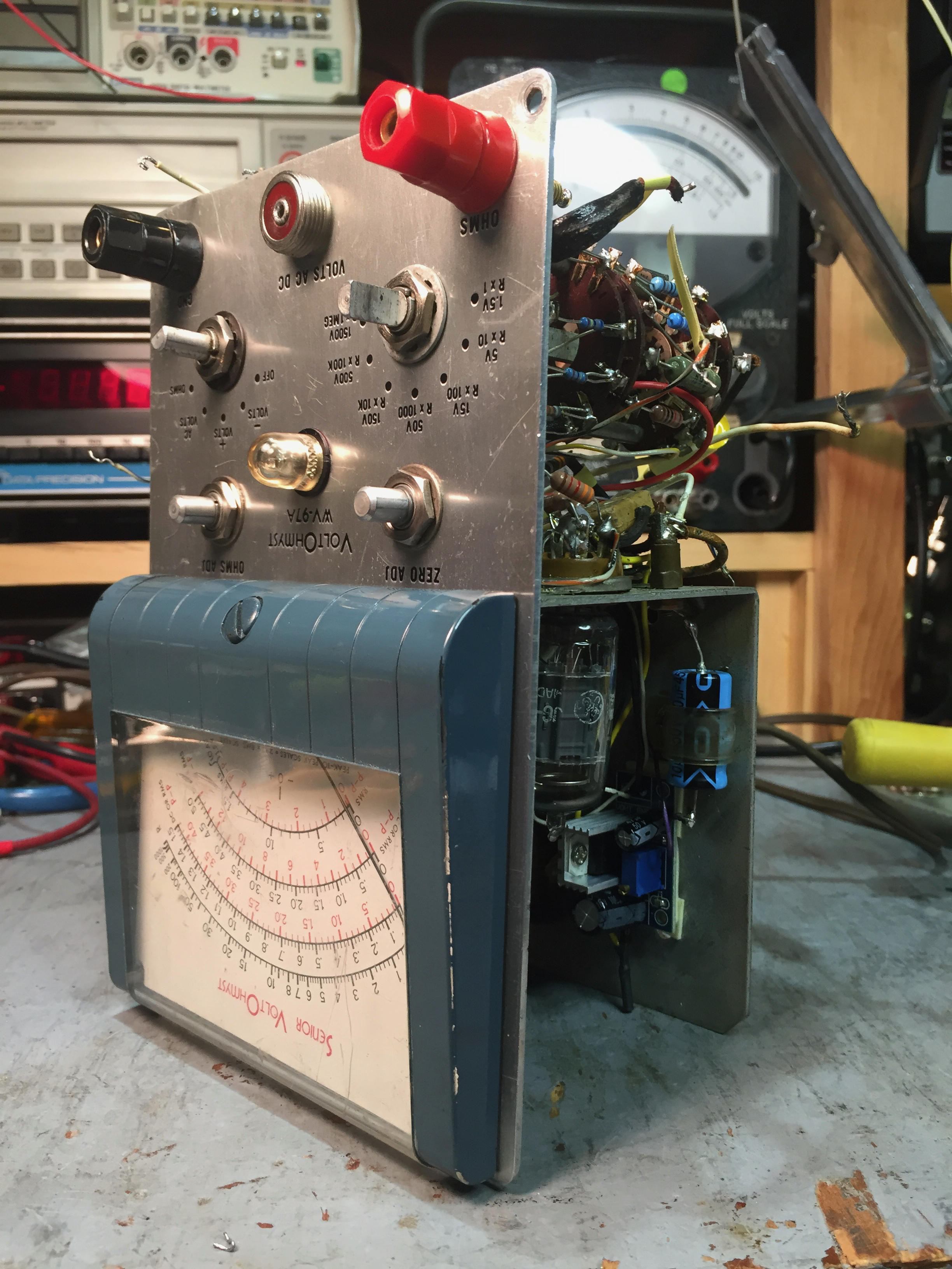
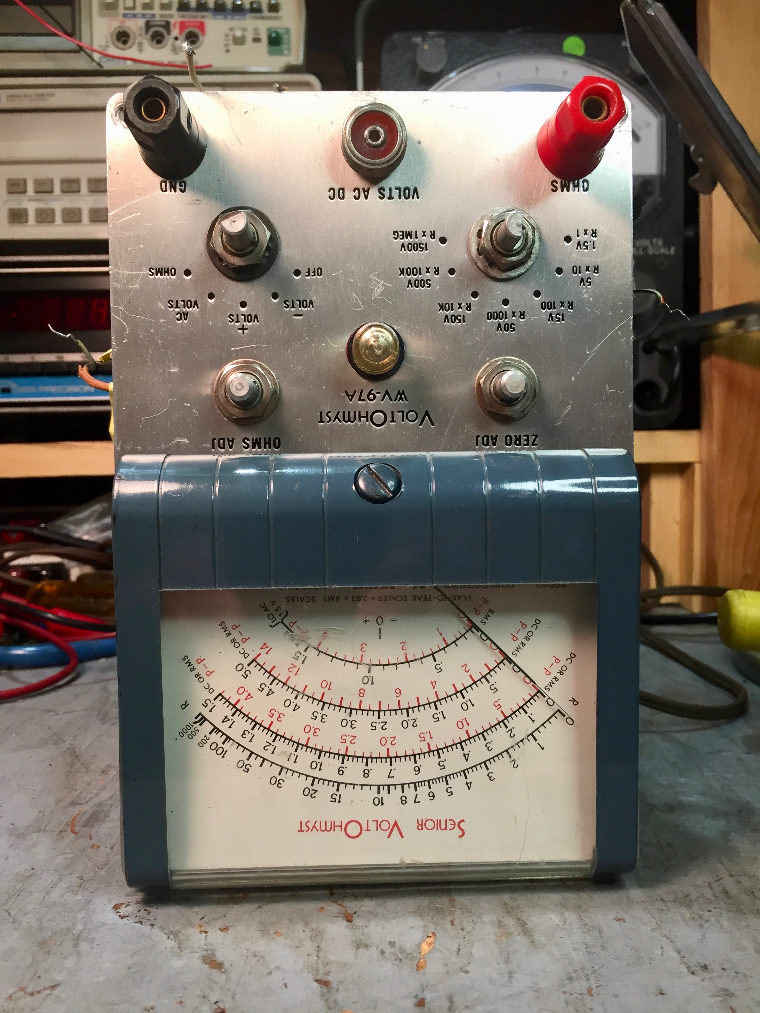
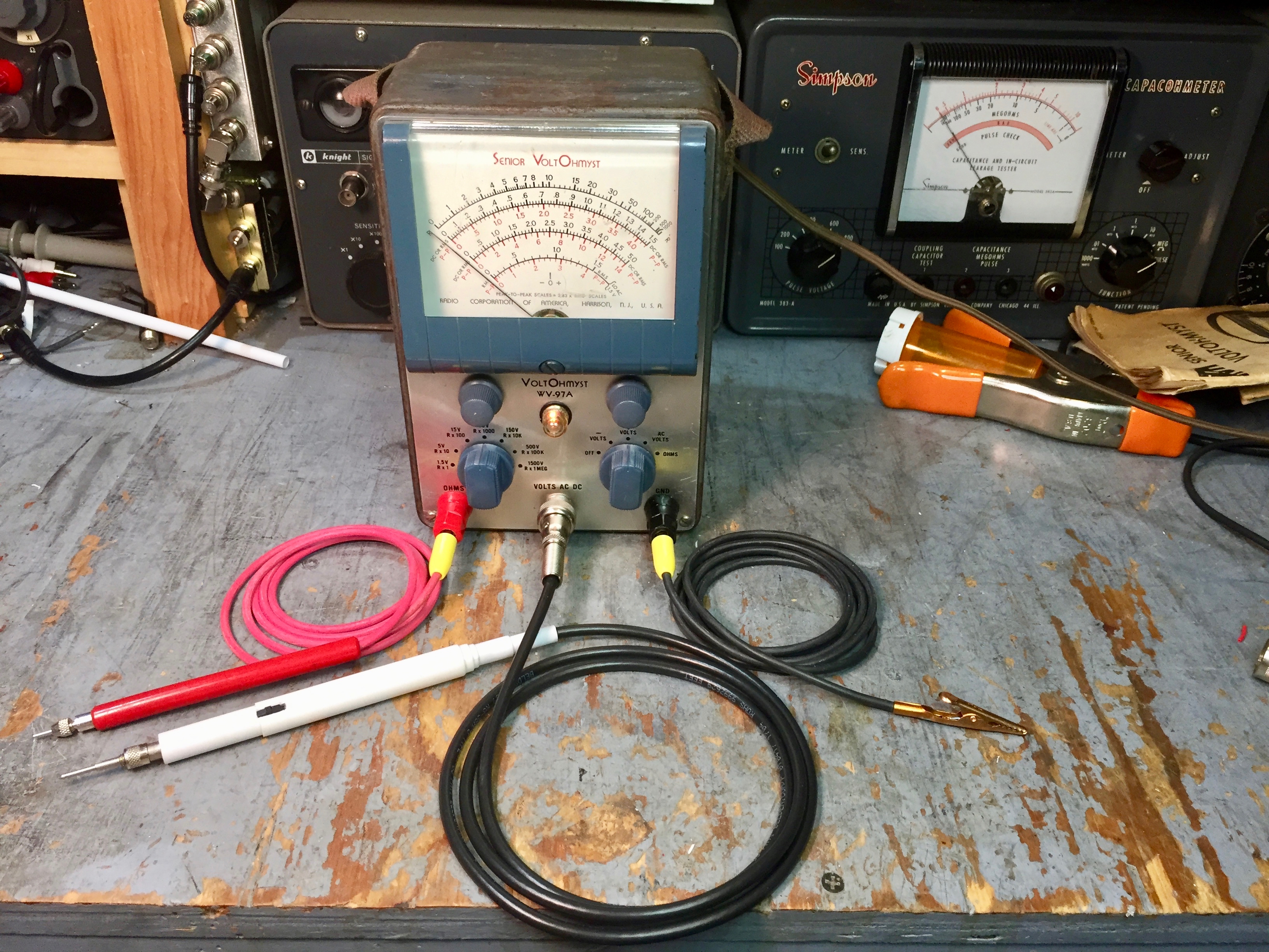
Yes, it is indeed a Type WV-97A.
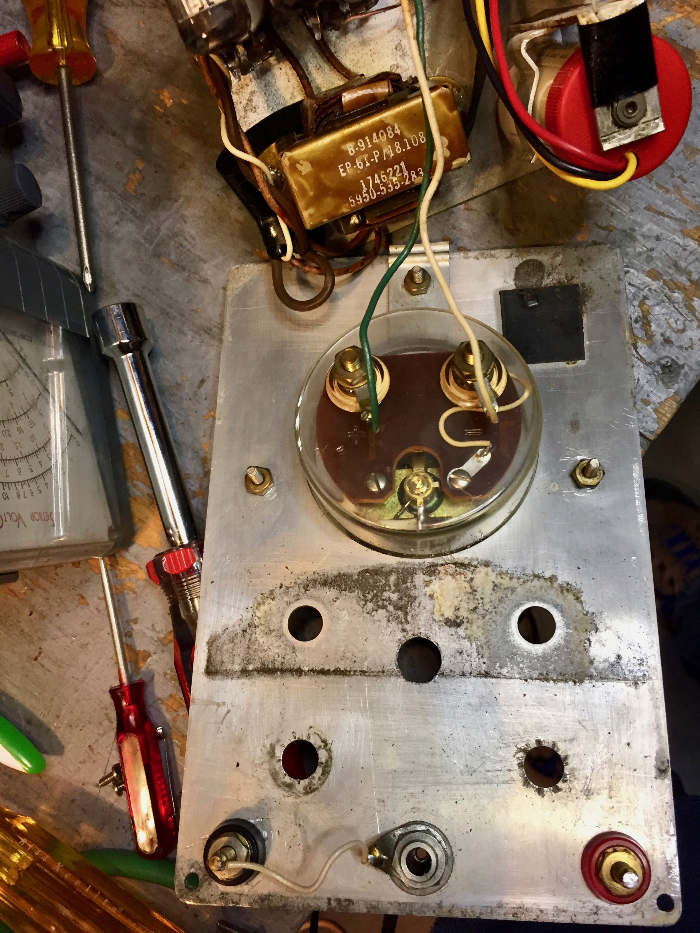
I cleaned the corrosion off the back of the front panel and the front of the chassis using a wire wheel in a hand-held drill.
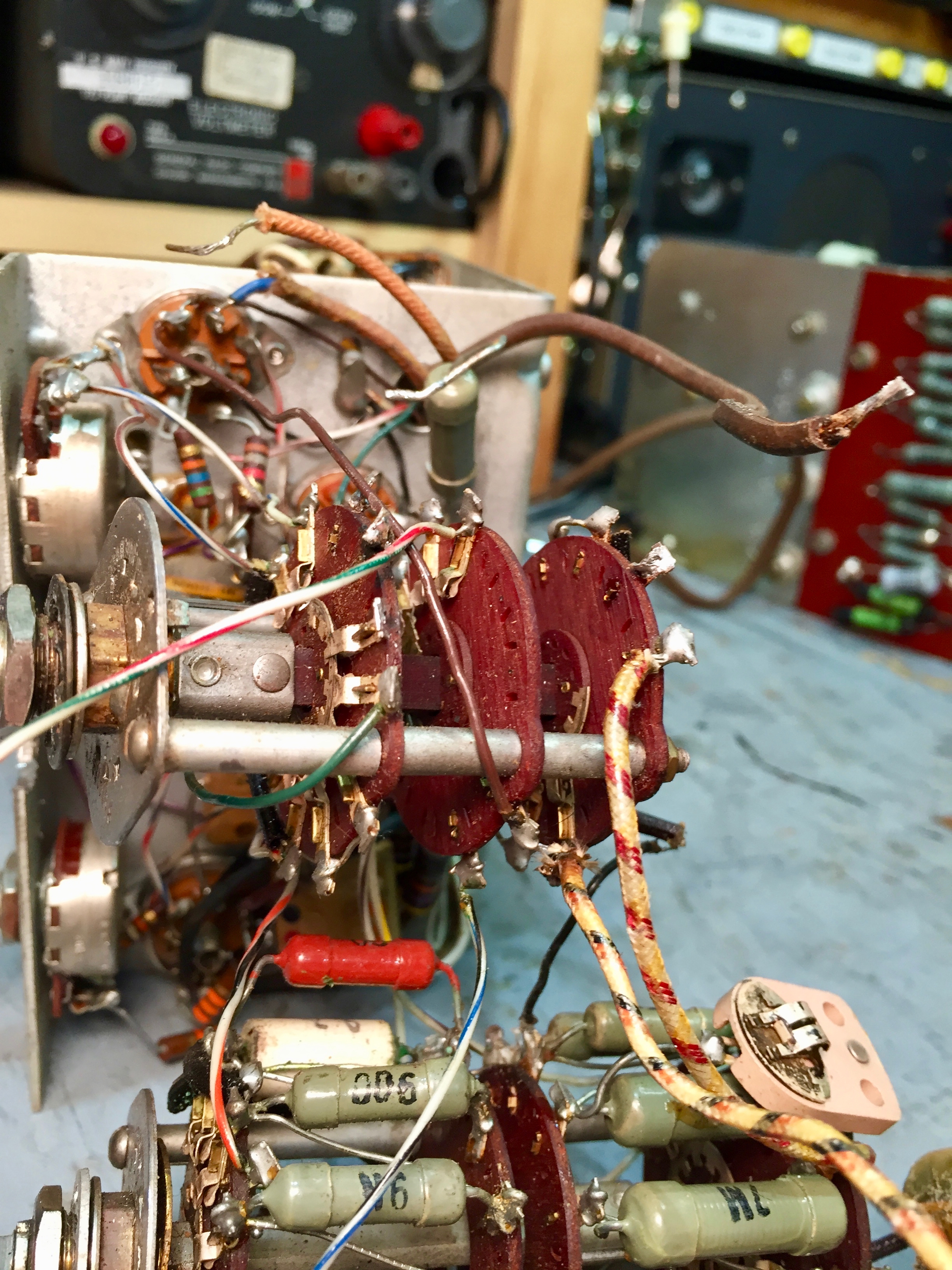
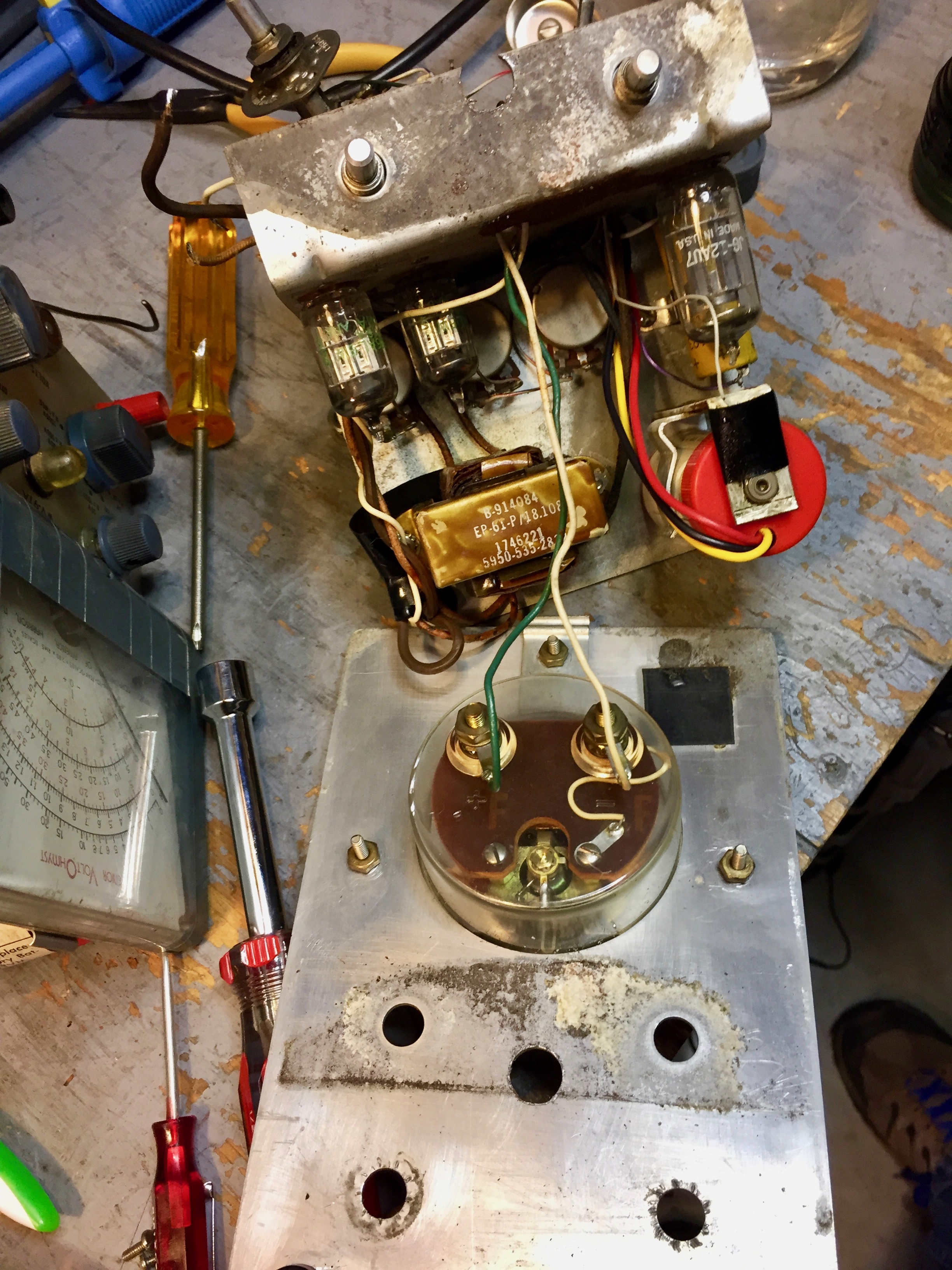
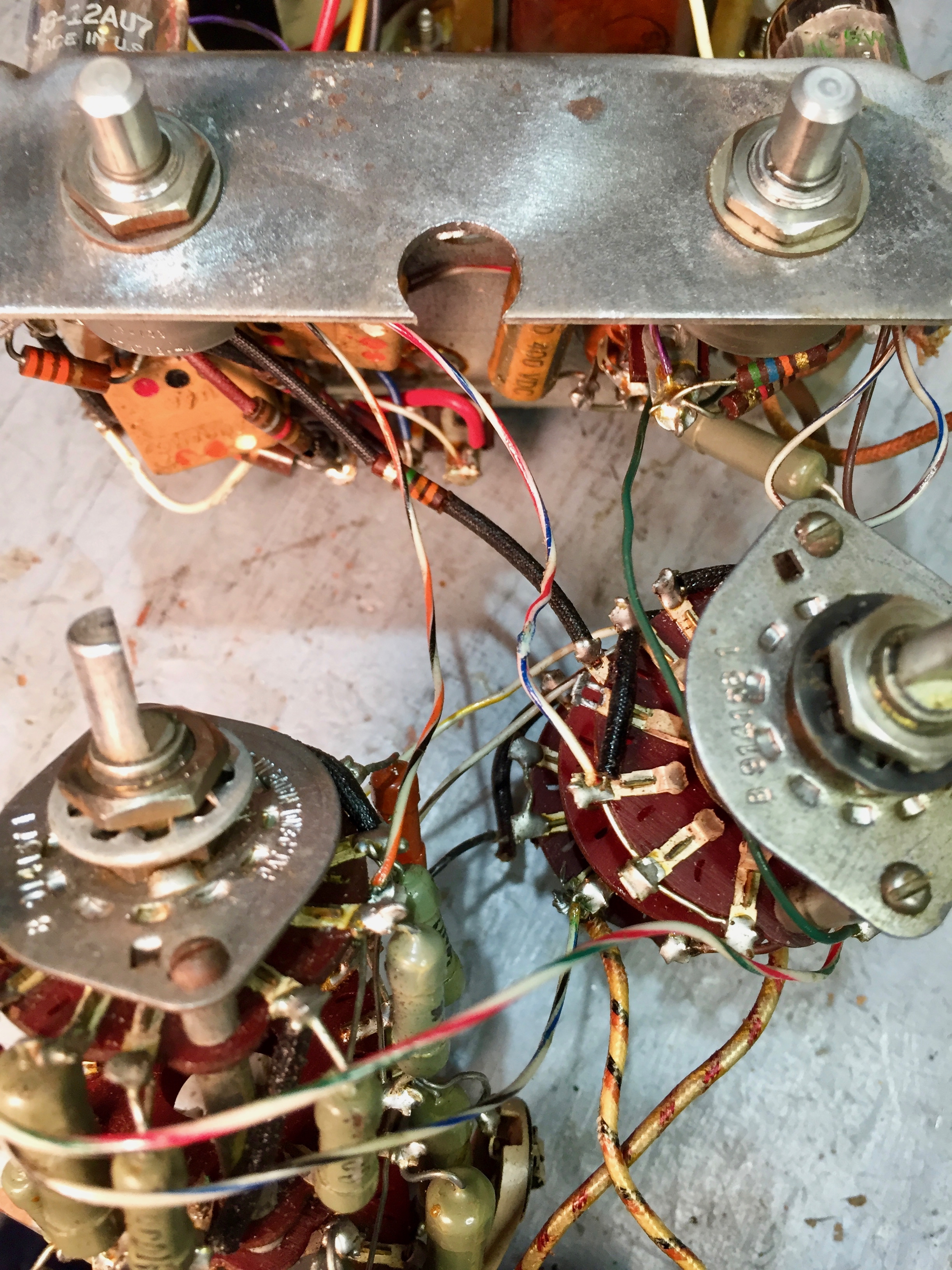
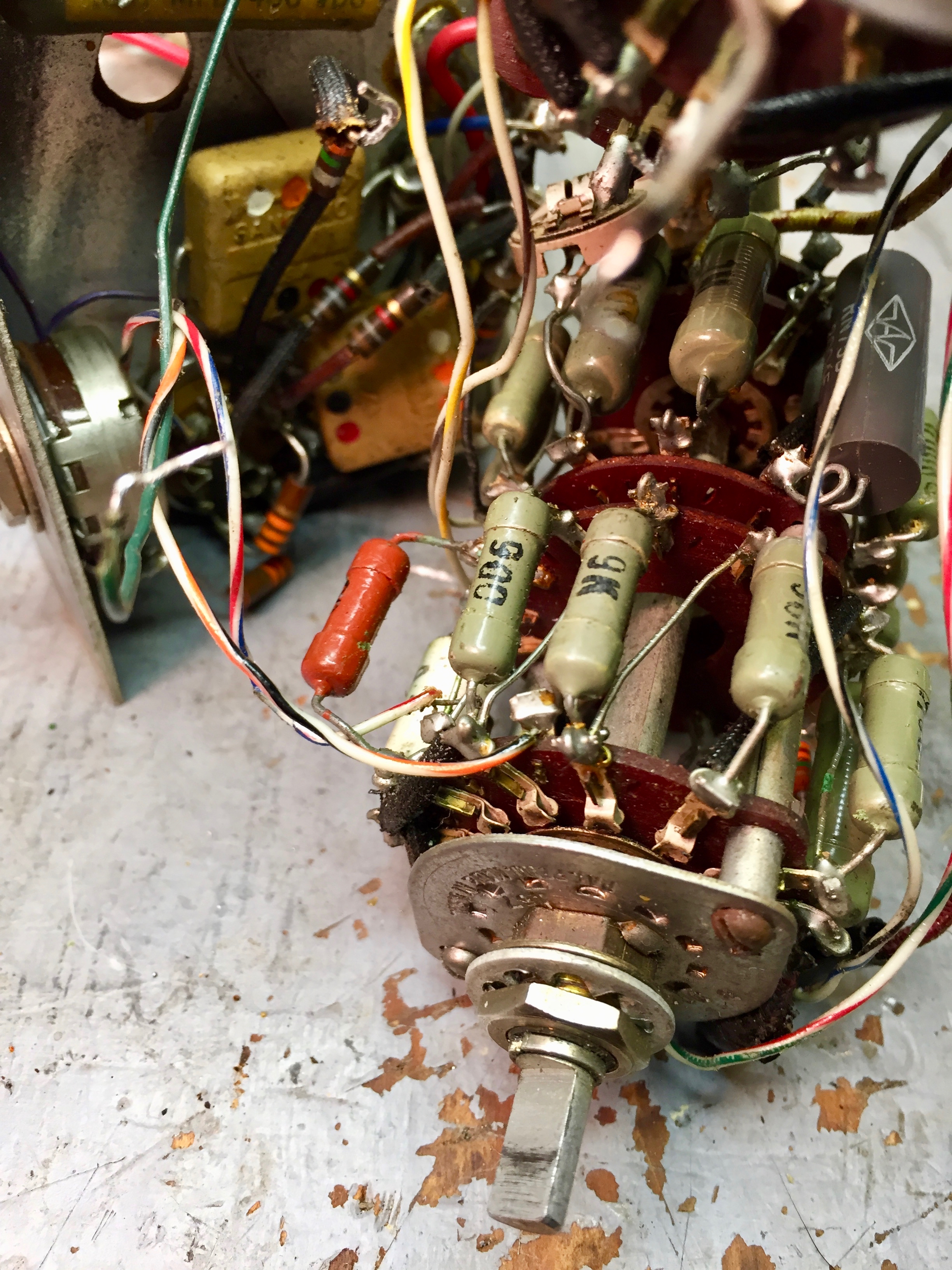
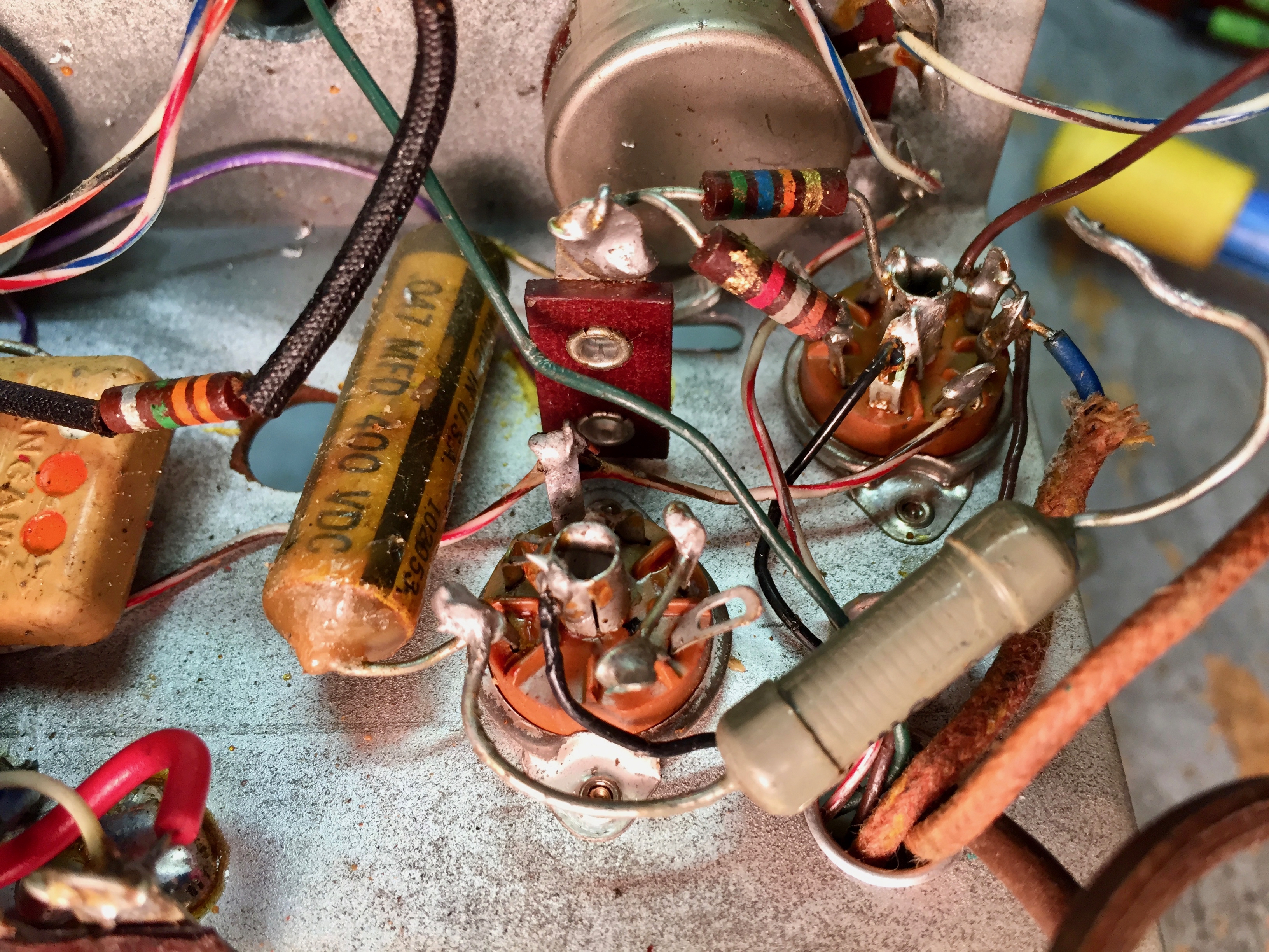
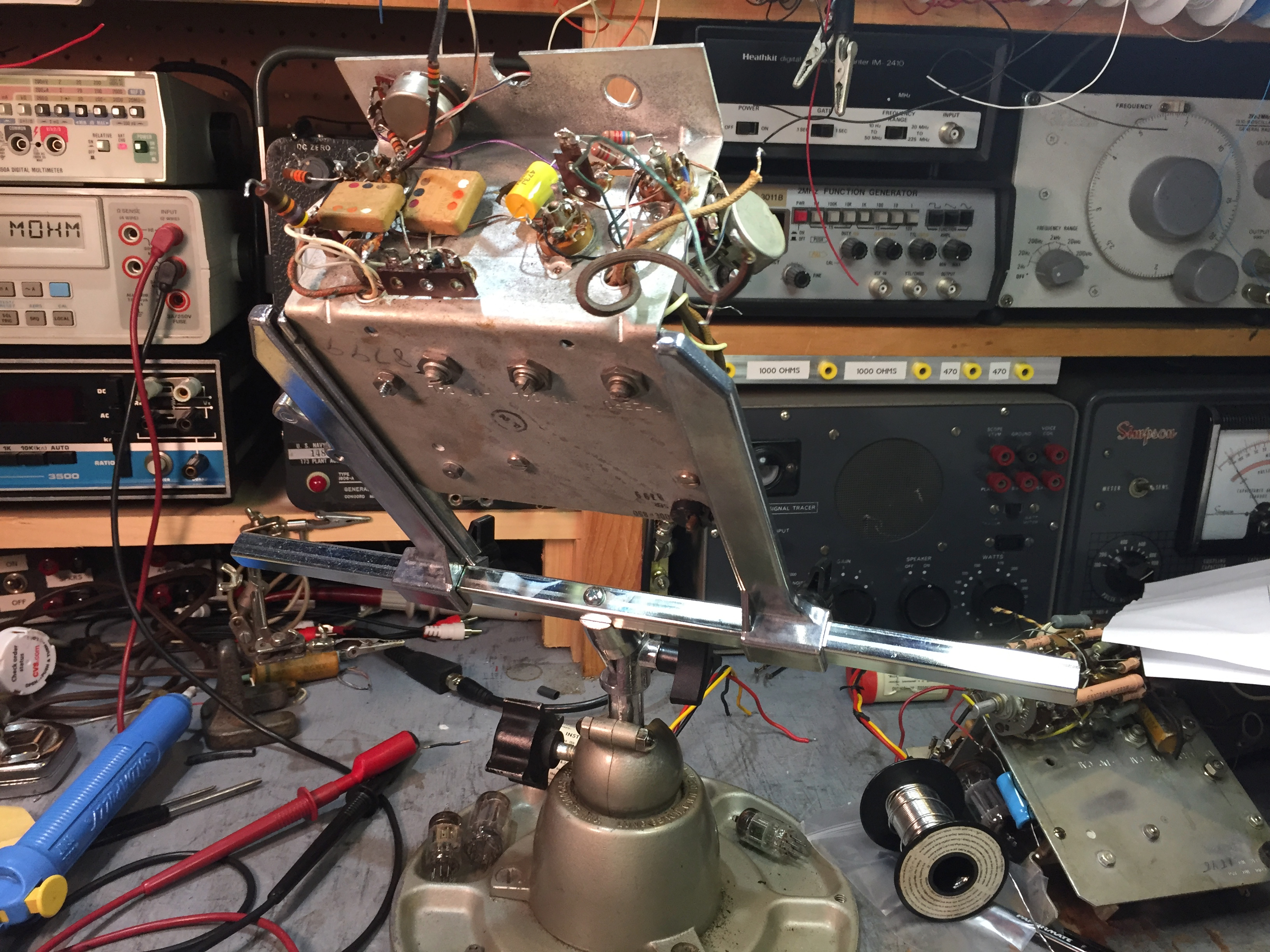
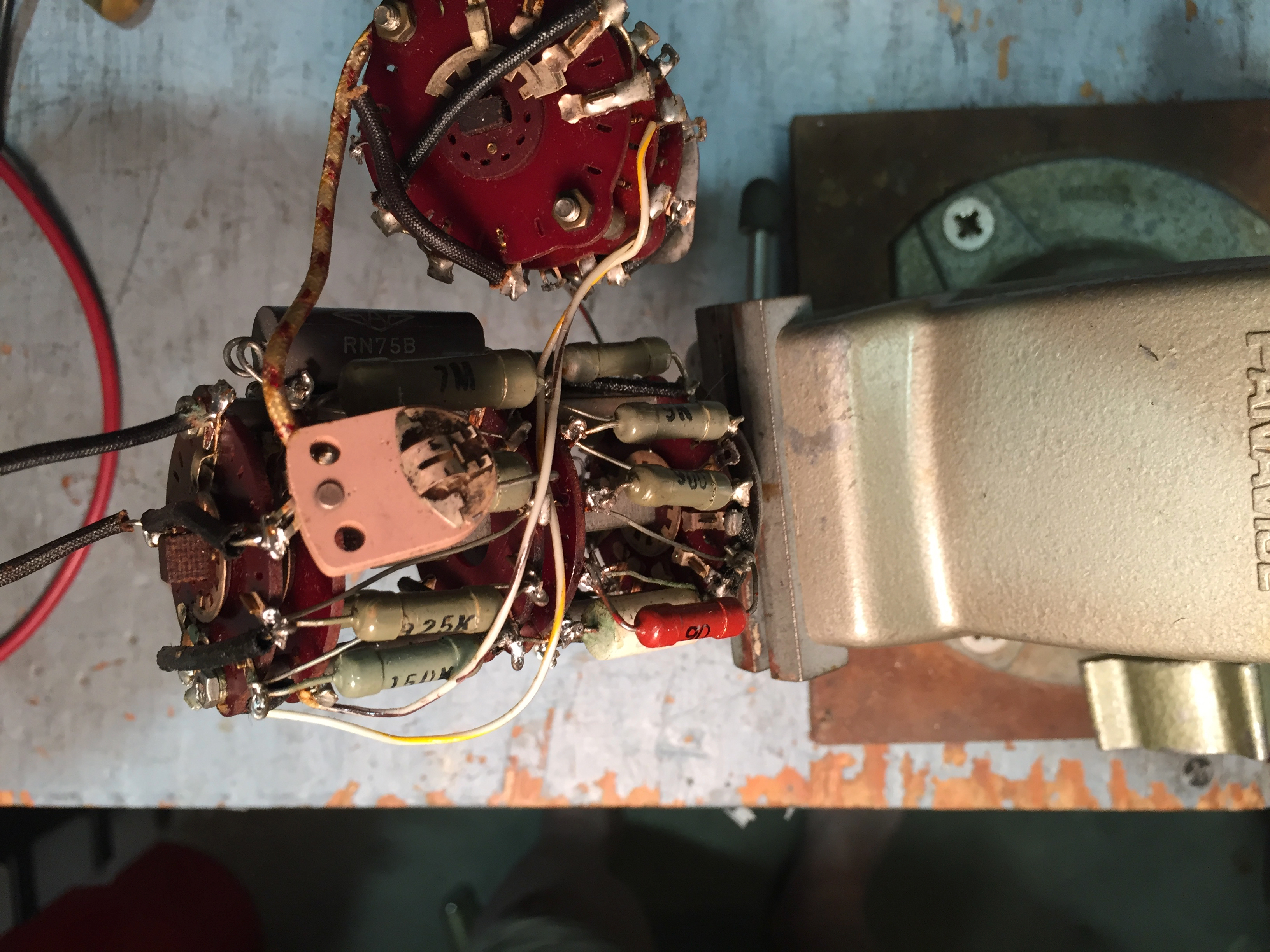
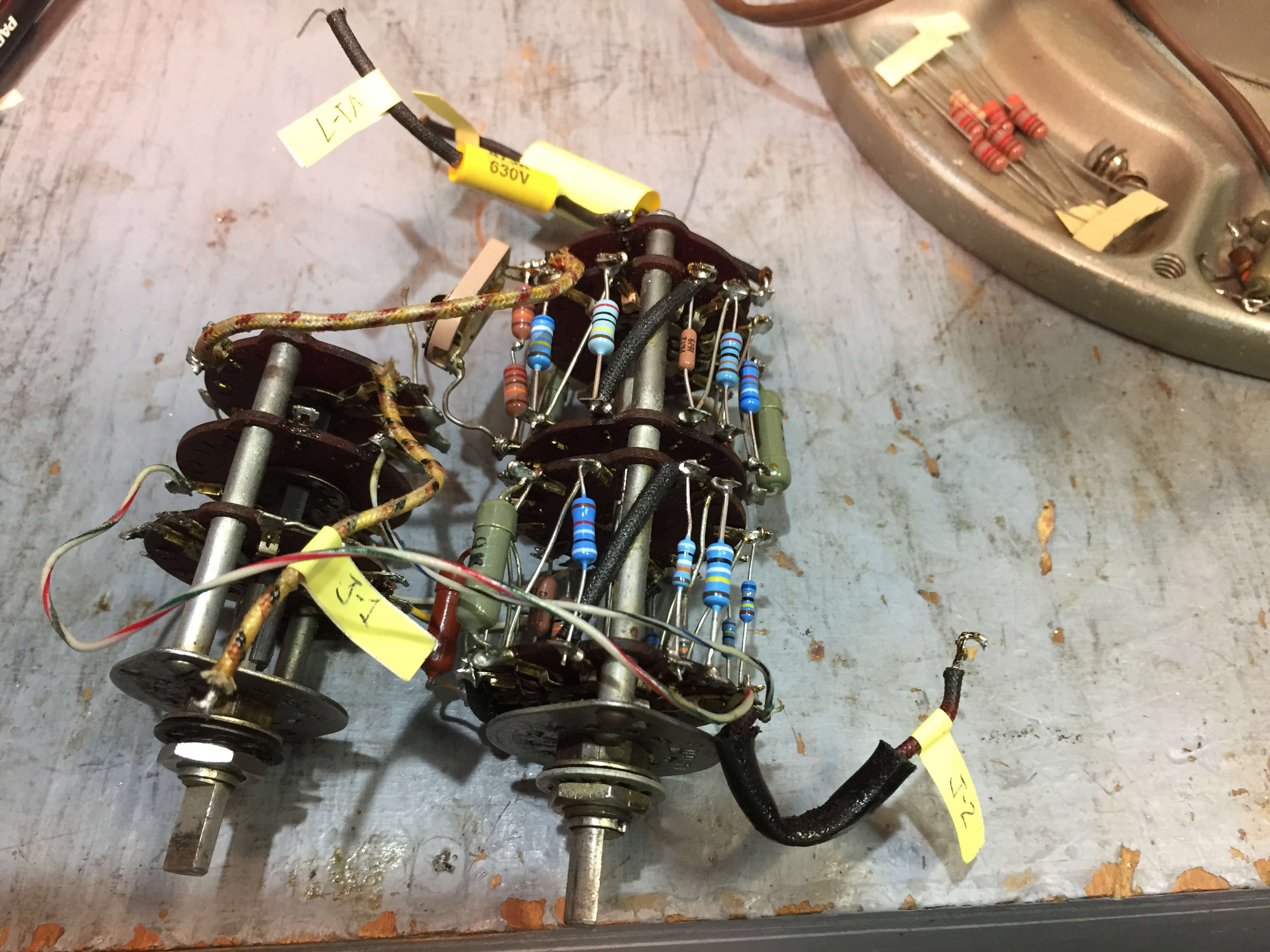
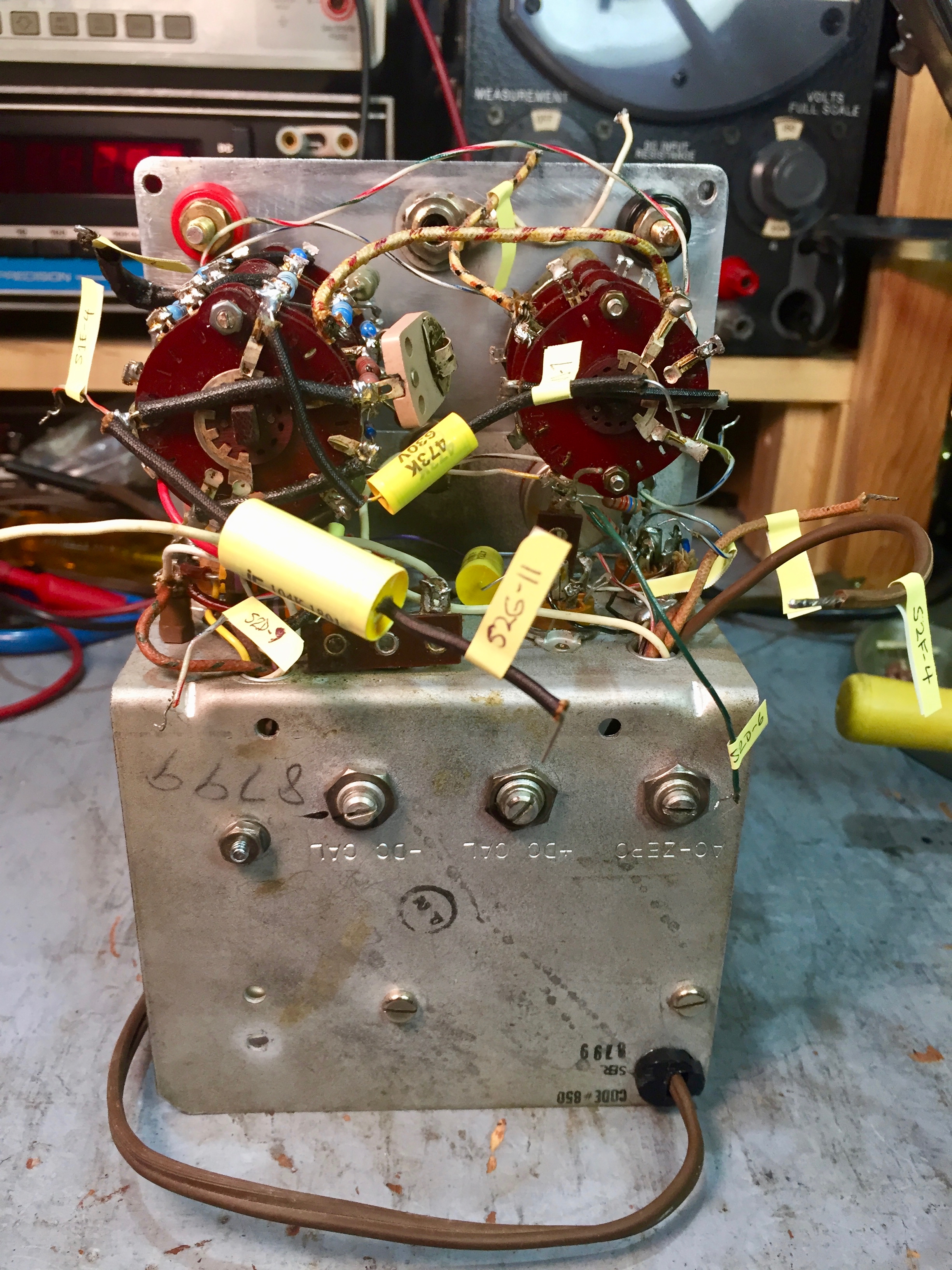
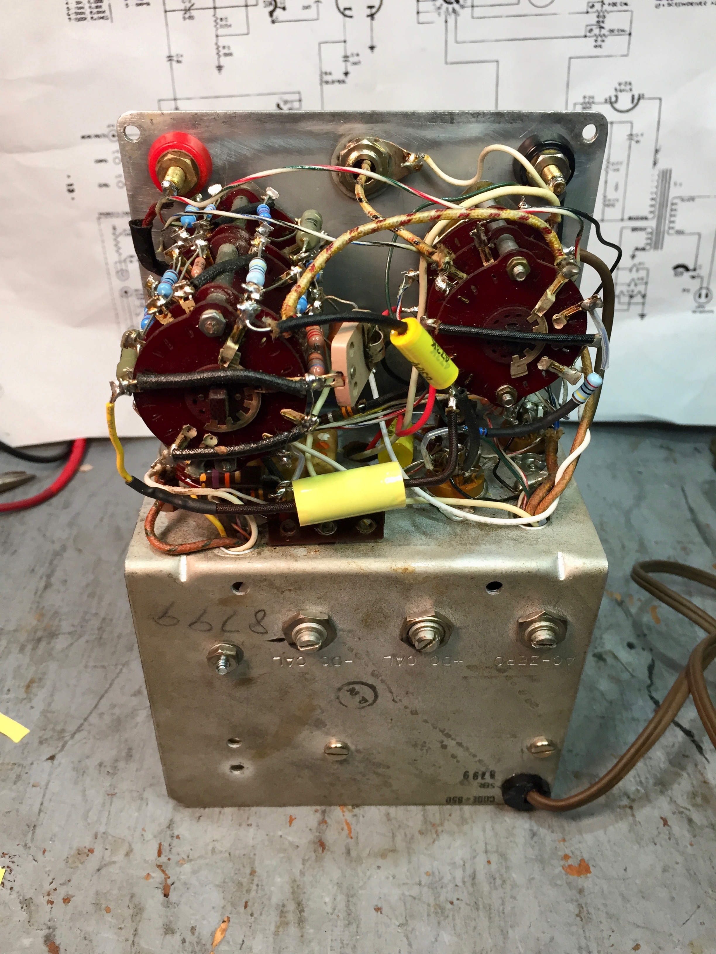
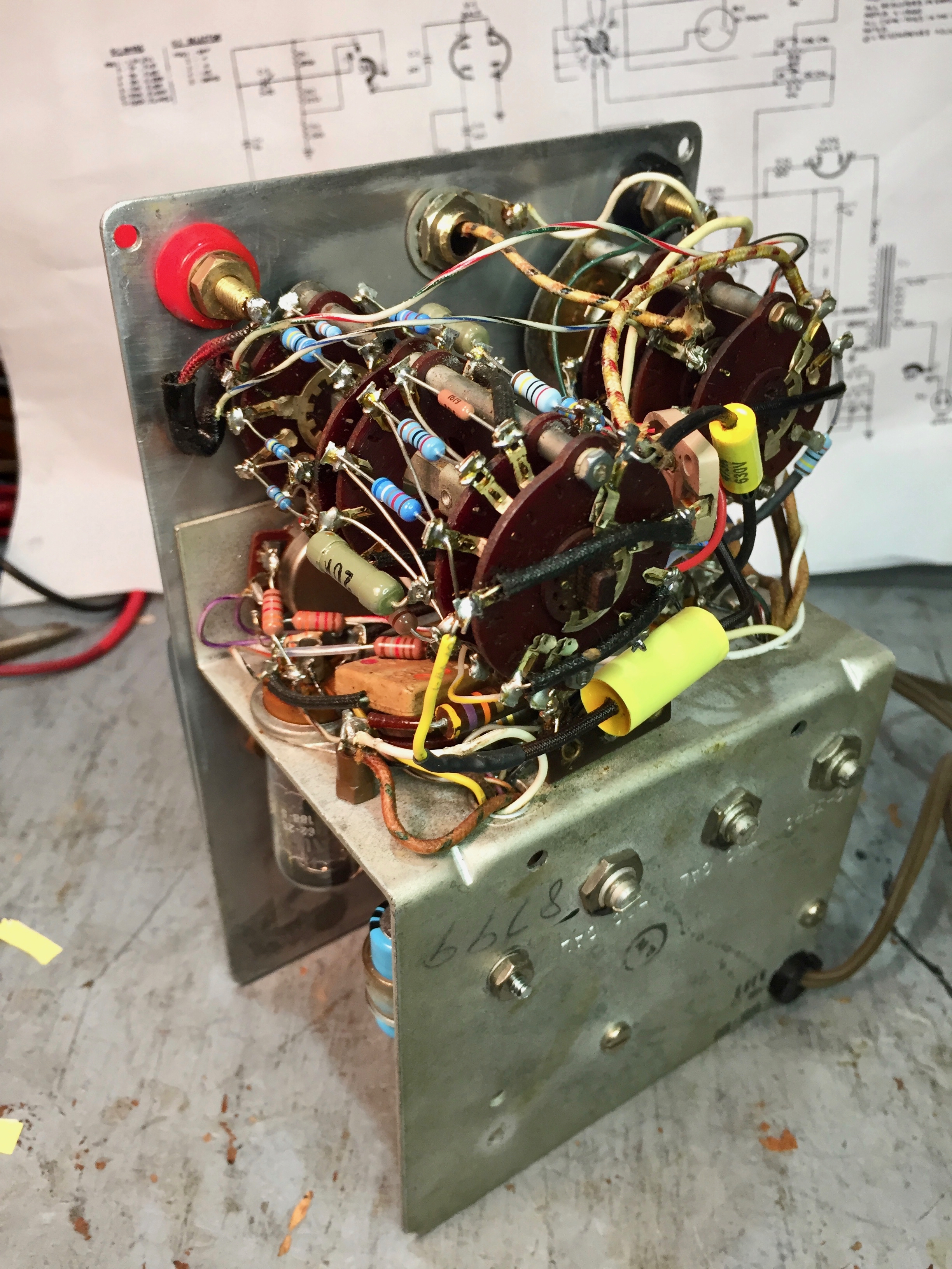
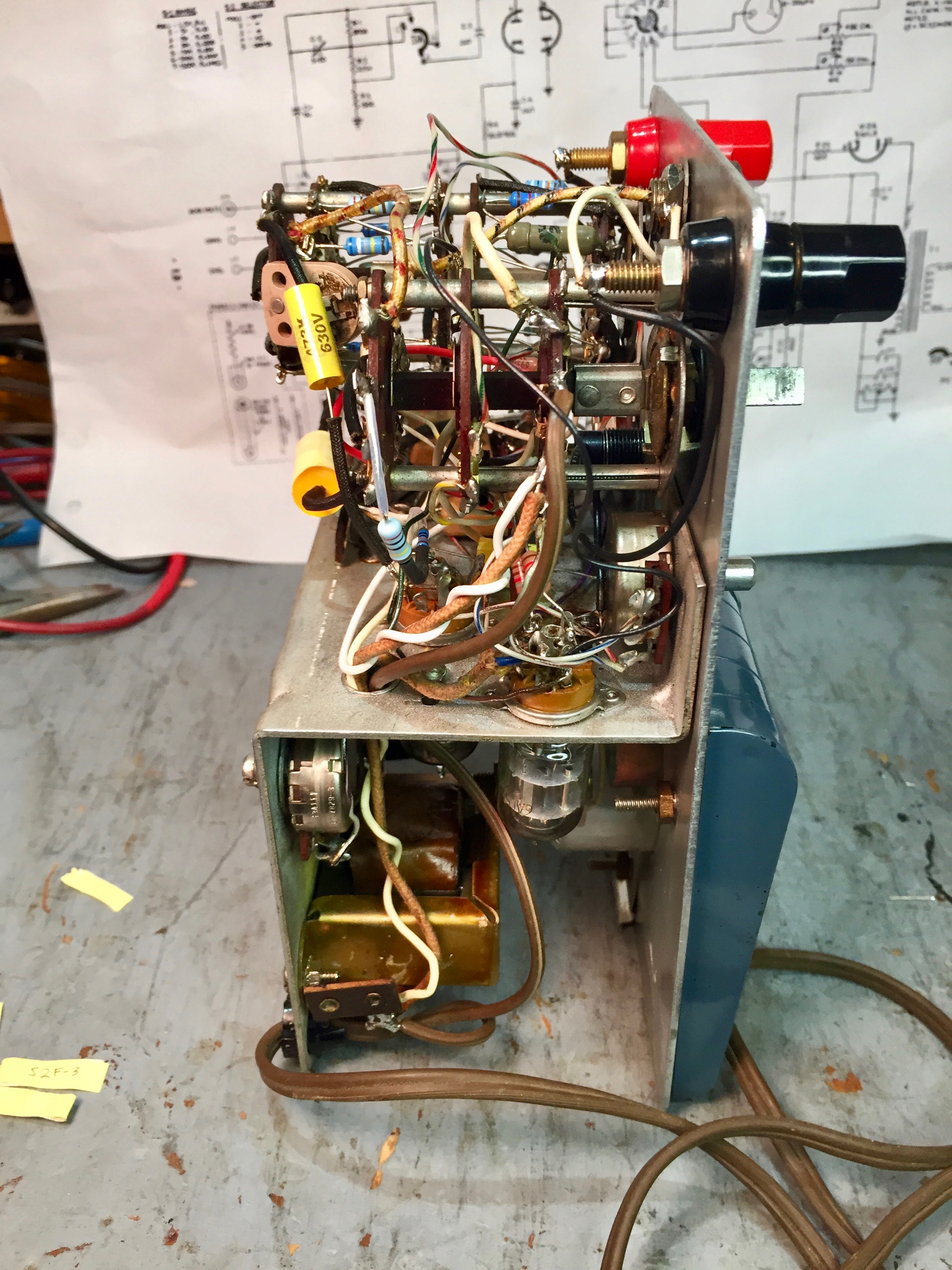
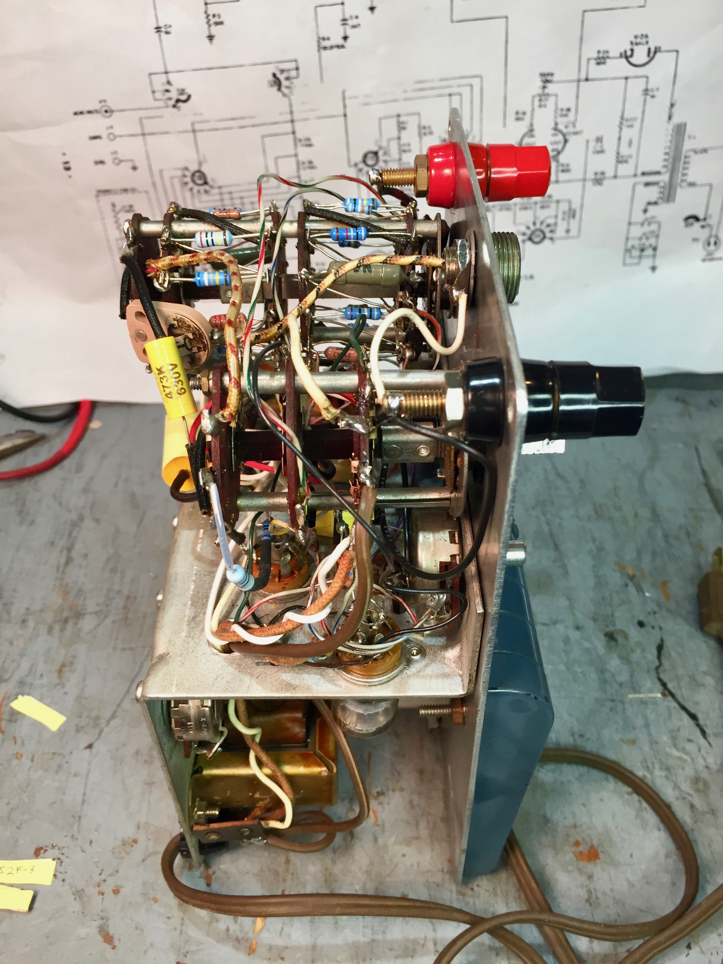
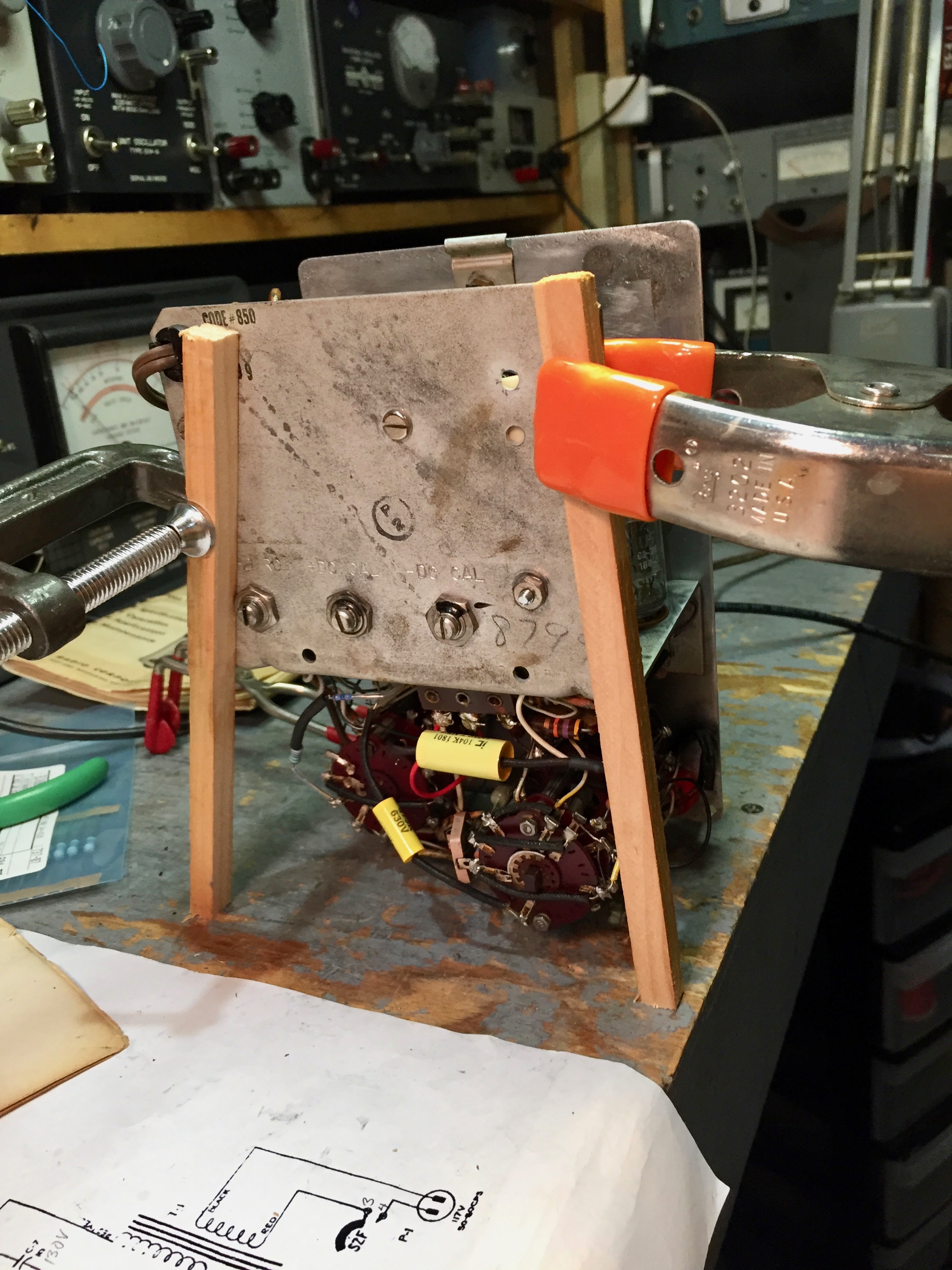
John’s unit is from run 850, a fairly modern version. Note that the precision resistors are mounted on the range switch. The chassis for a run 350 version is visible (but out of focus) in the background to the upper right.
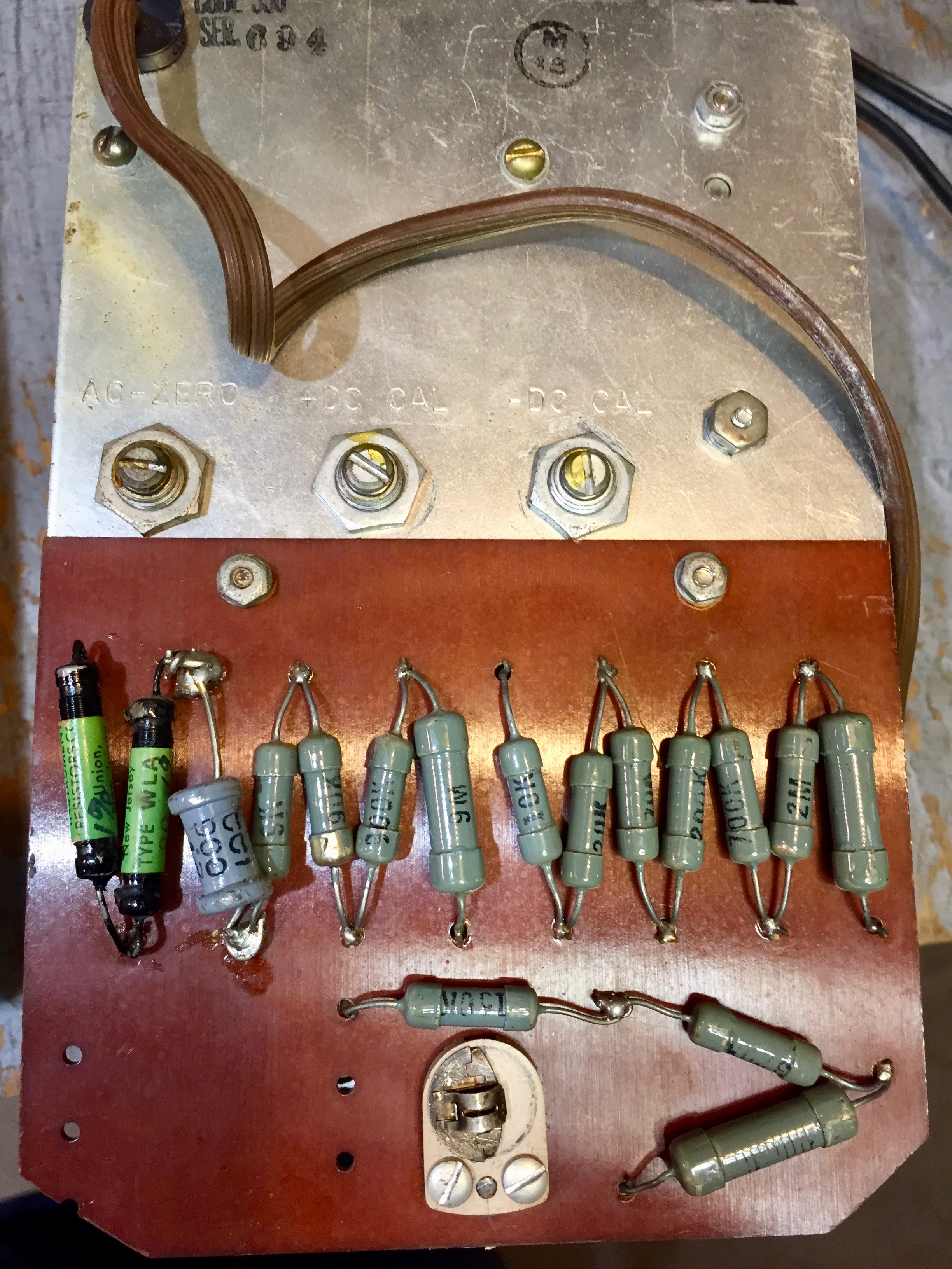
Note that in the run 350 variant, the precision resistors are mounted to a tag board attached to the chassis, rather than mounted on the range switch.
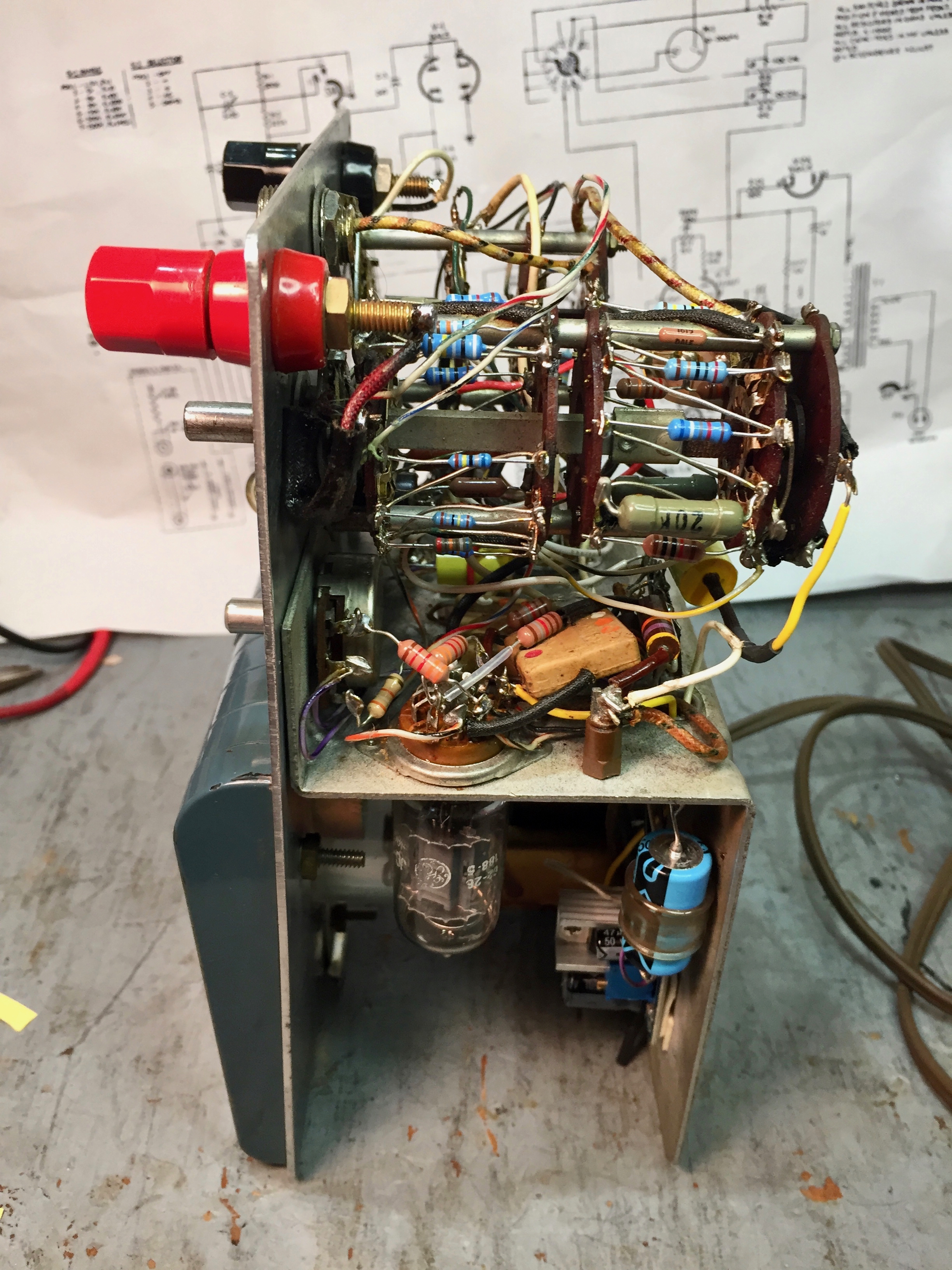
The later unit also has teflon-insulated hookup wire, a very nice touch. Teflon is quite resistant to melting when being soldered. It’s also pretty pricey, so I was surprised to see RCA used it in a service-grade instrument.
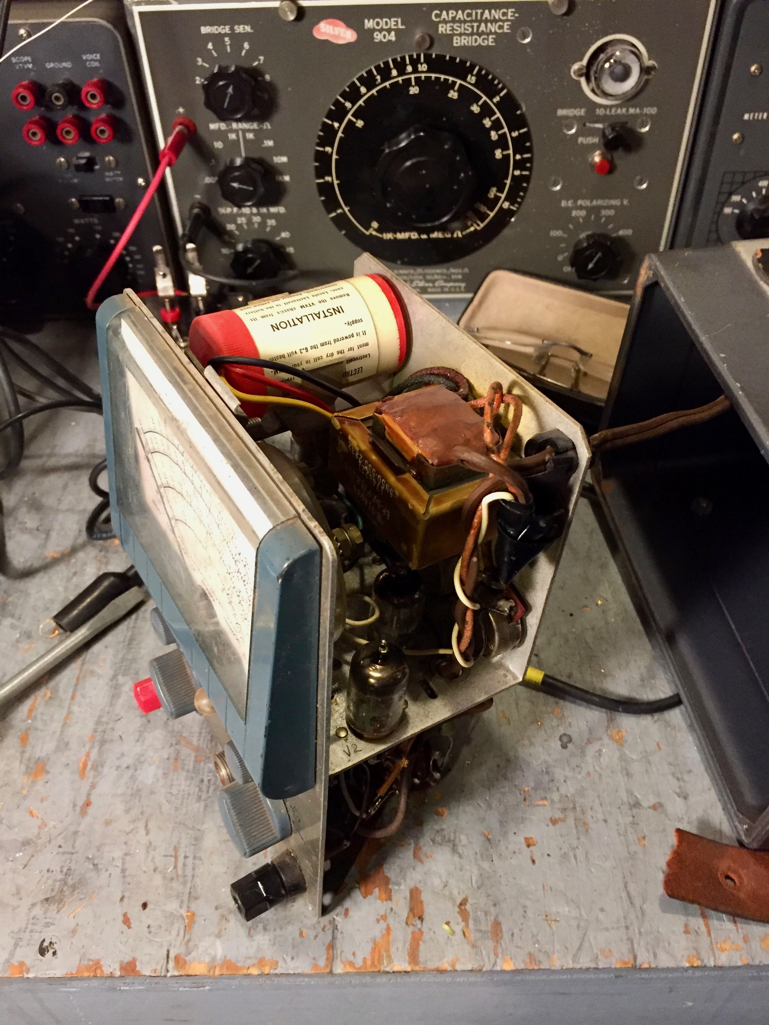
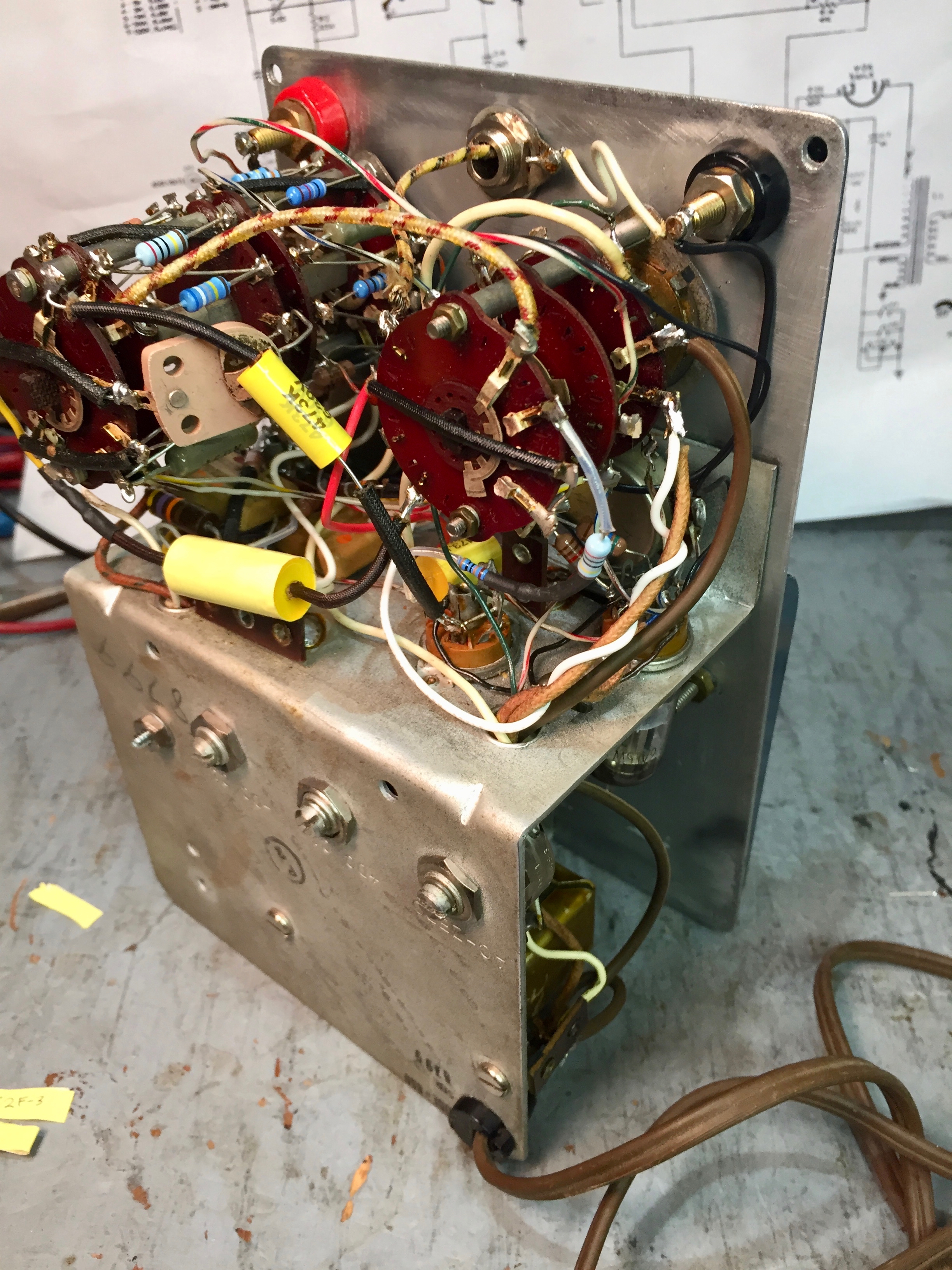
Even with the front panel removed, there wasn’t enough slack in the wires between the switches and the chassis to work,
so I started disconnecting the range and function switches from the chassis. I had to work up my nerve a bit before taking this step. Again, I took lots of photos to help get everything back together correctly.
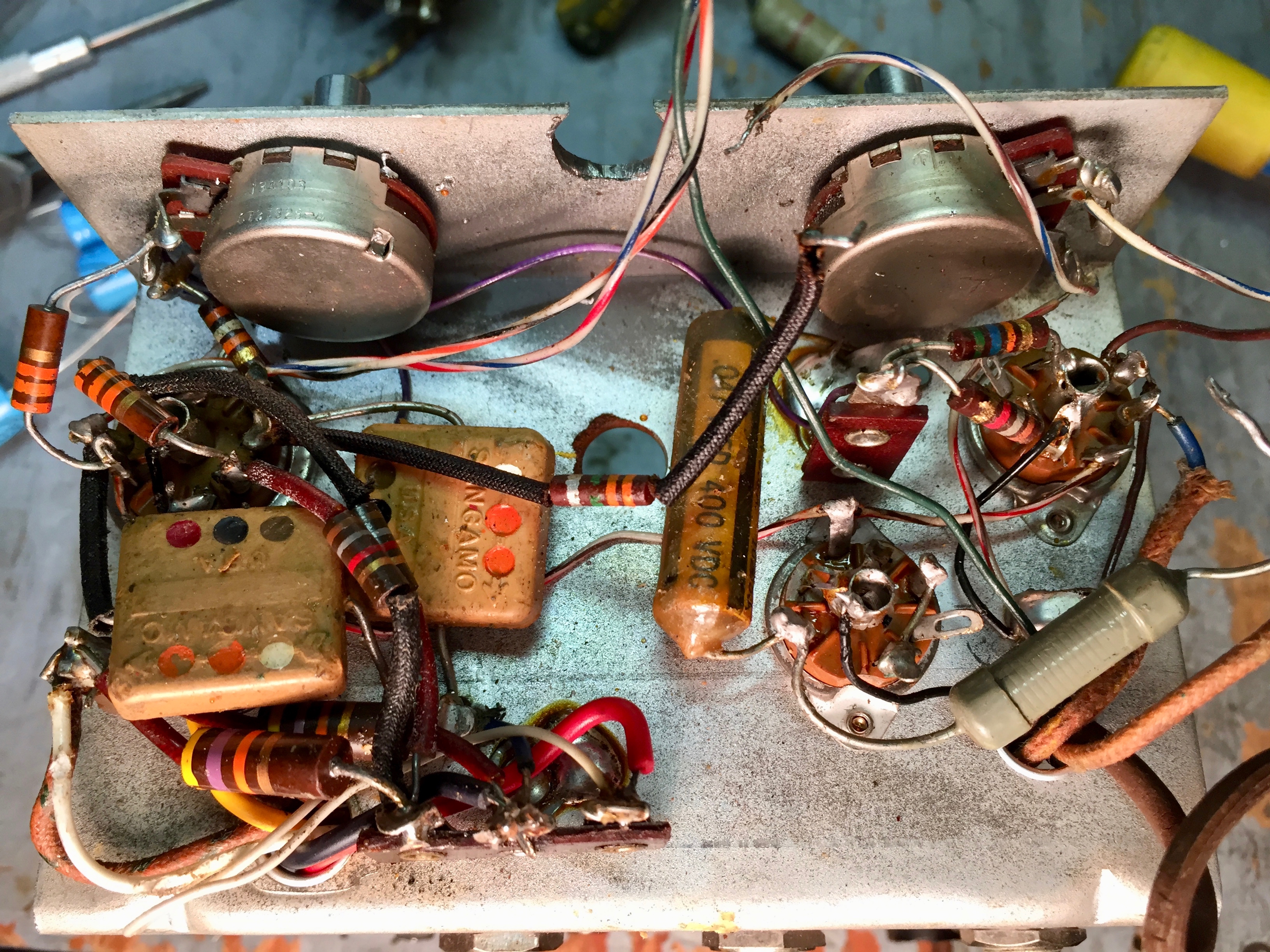
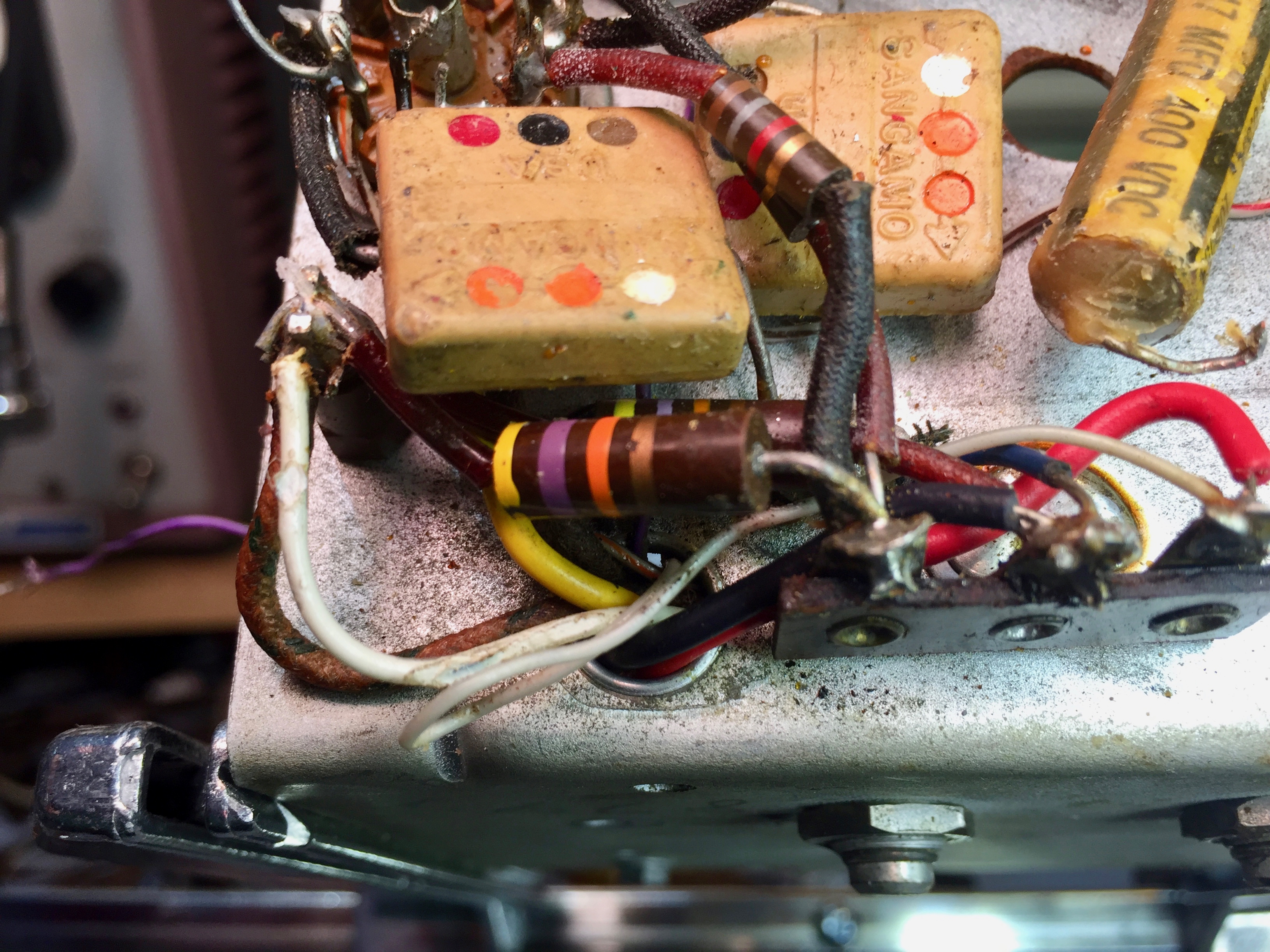
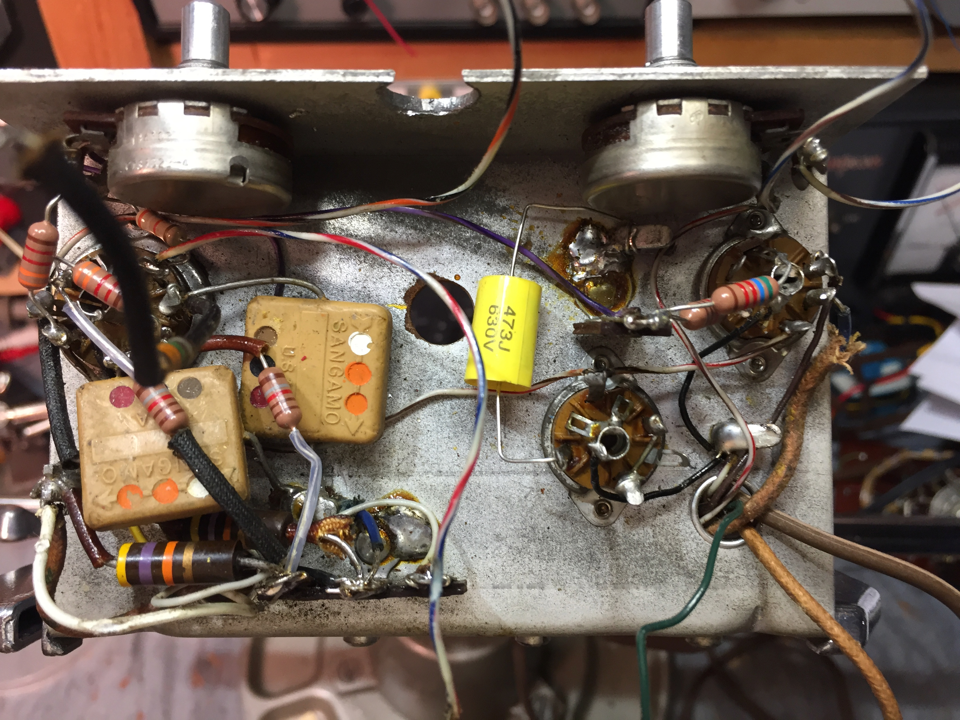
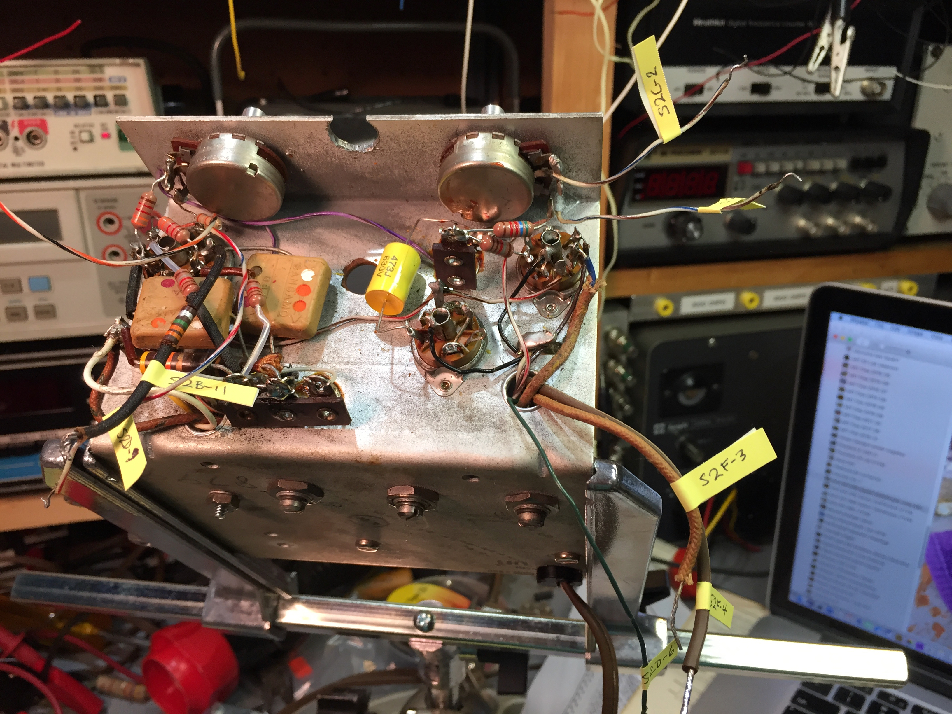
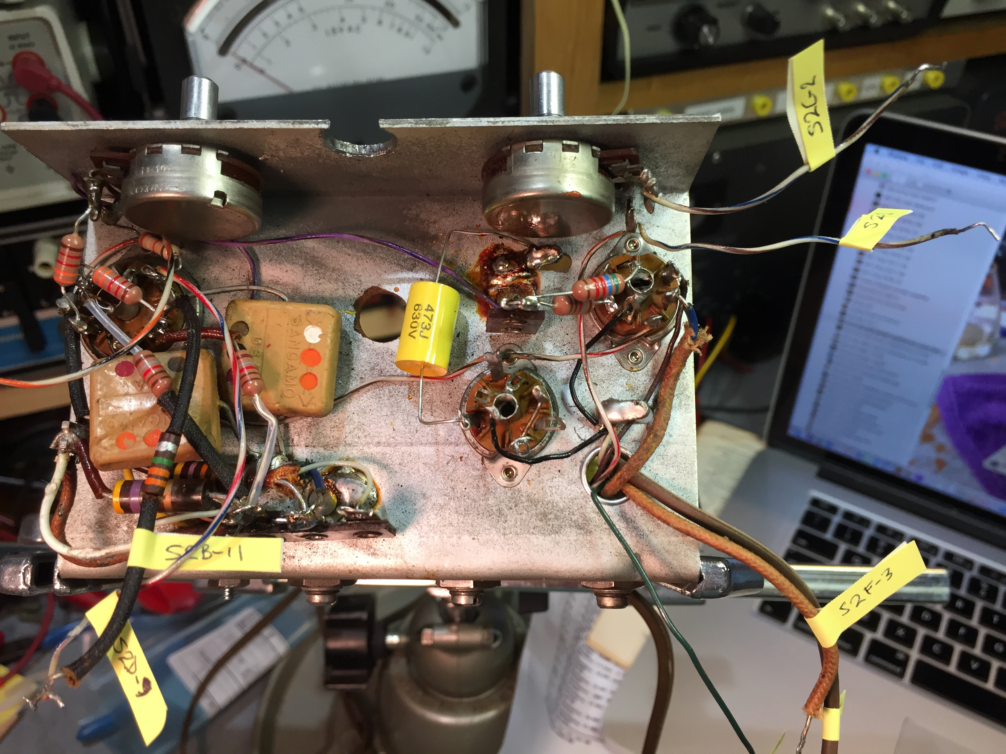
Here’s a view of the chassis, minus the range and function switches. I don’t remember if I tested the mica caps. I’ll have to retest them when I get back home (we’re on vacation as I write this). I'll replace the paper capacitors as a matter of course.
The 47KΩ 1/2 watt resistors have been replaced with 1 watt carbon composition resistors. The replacements are still in spec.
Most of the rest of the resistors need to be replaced, so again I took lots of photos to help get the replacements in the right place.
I’m wishing I had some good wiring diagrams for the WV-97A.
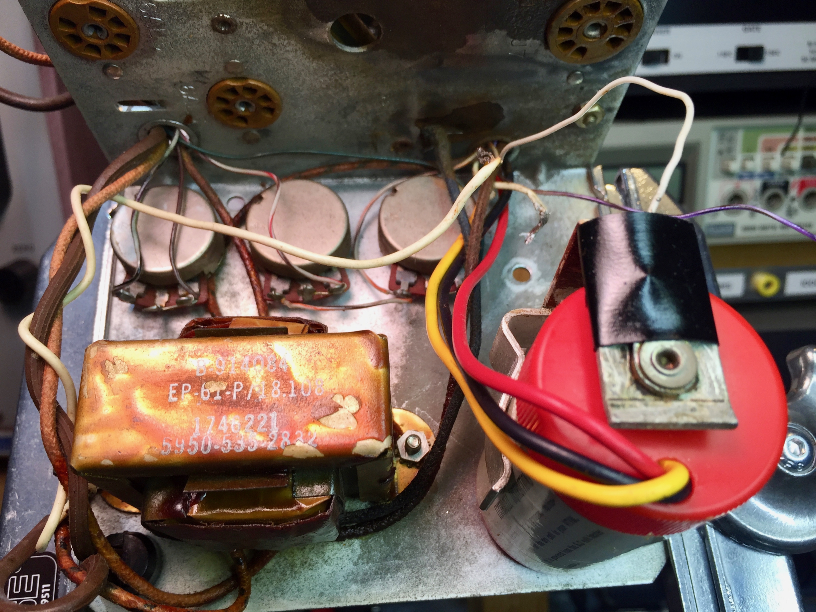
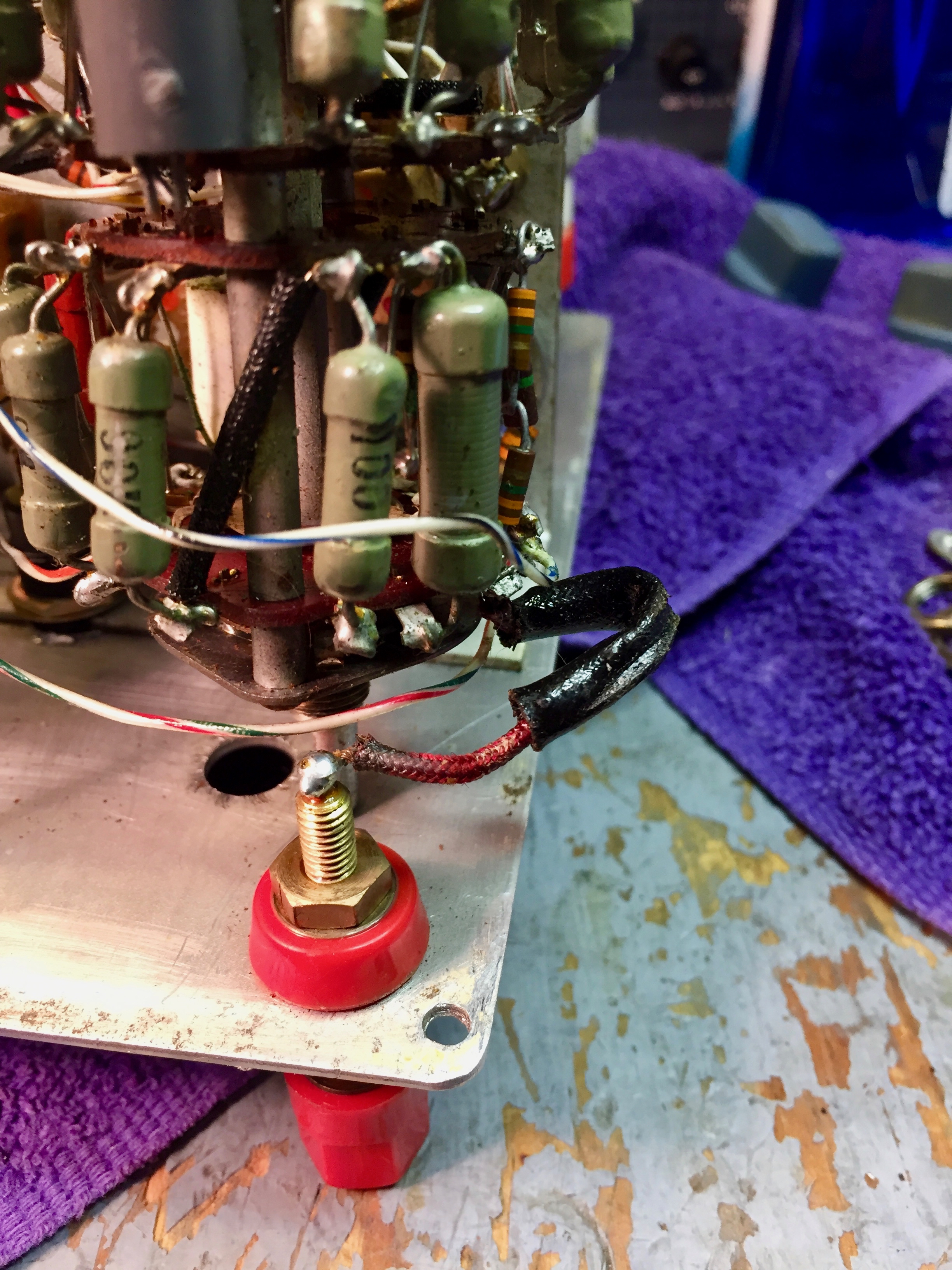
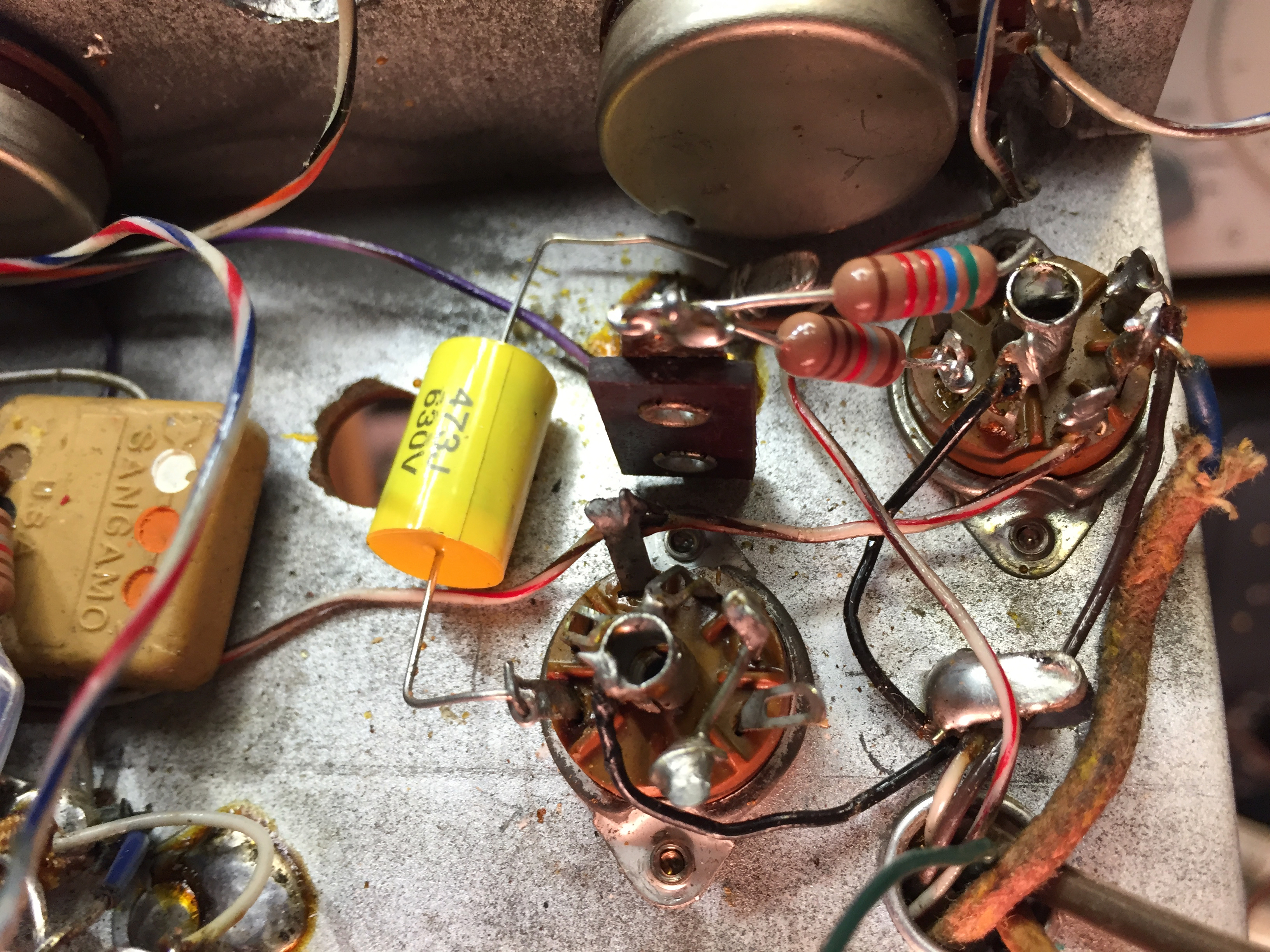
I’m replacing the Lectrocell with a modern battery eliminator based on an LM317, so I’ve got to remove the old Lectrocell wiring.
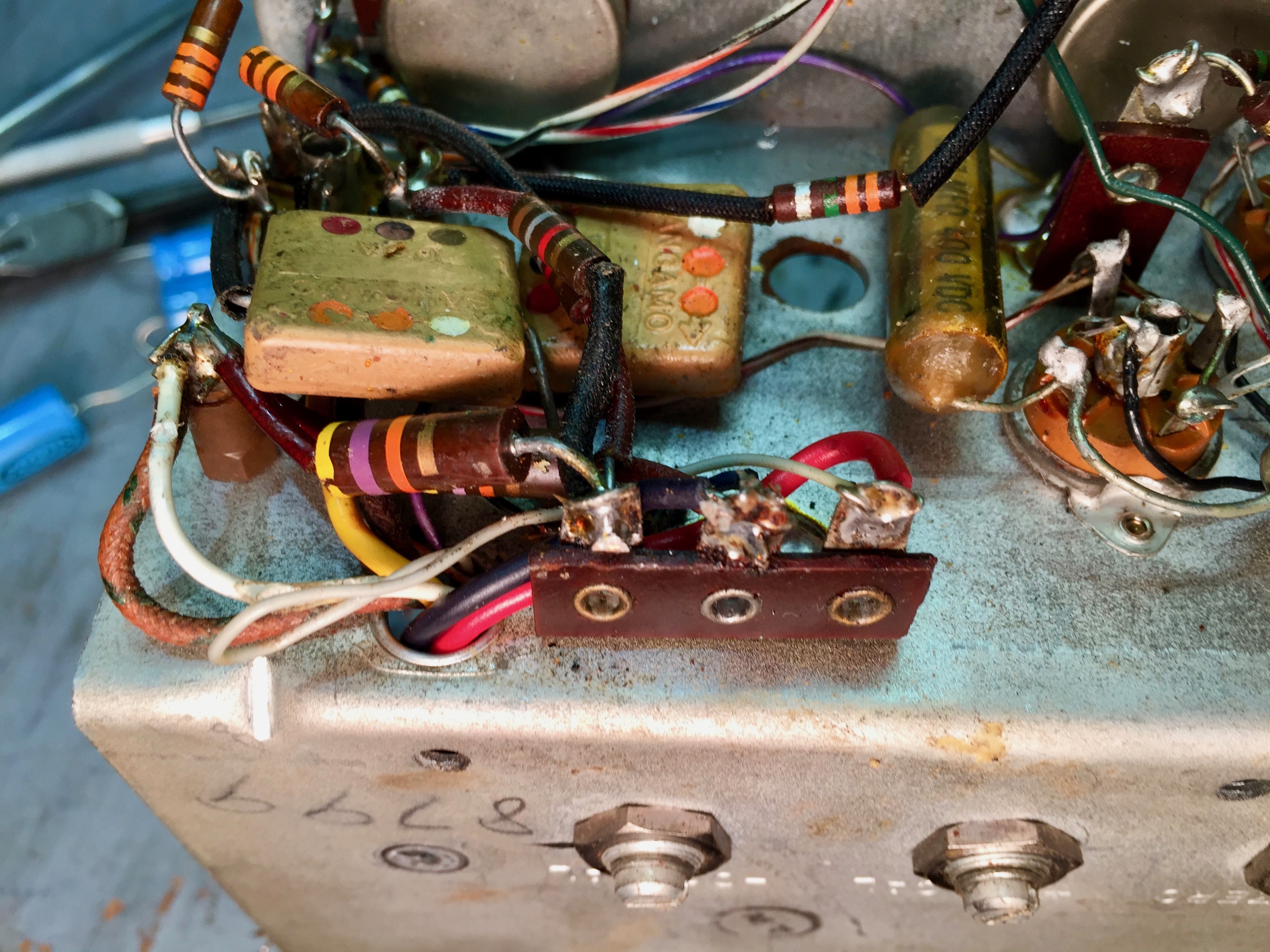
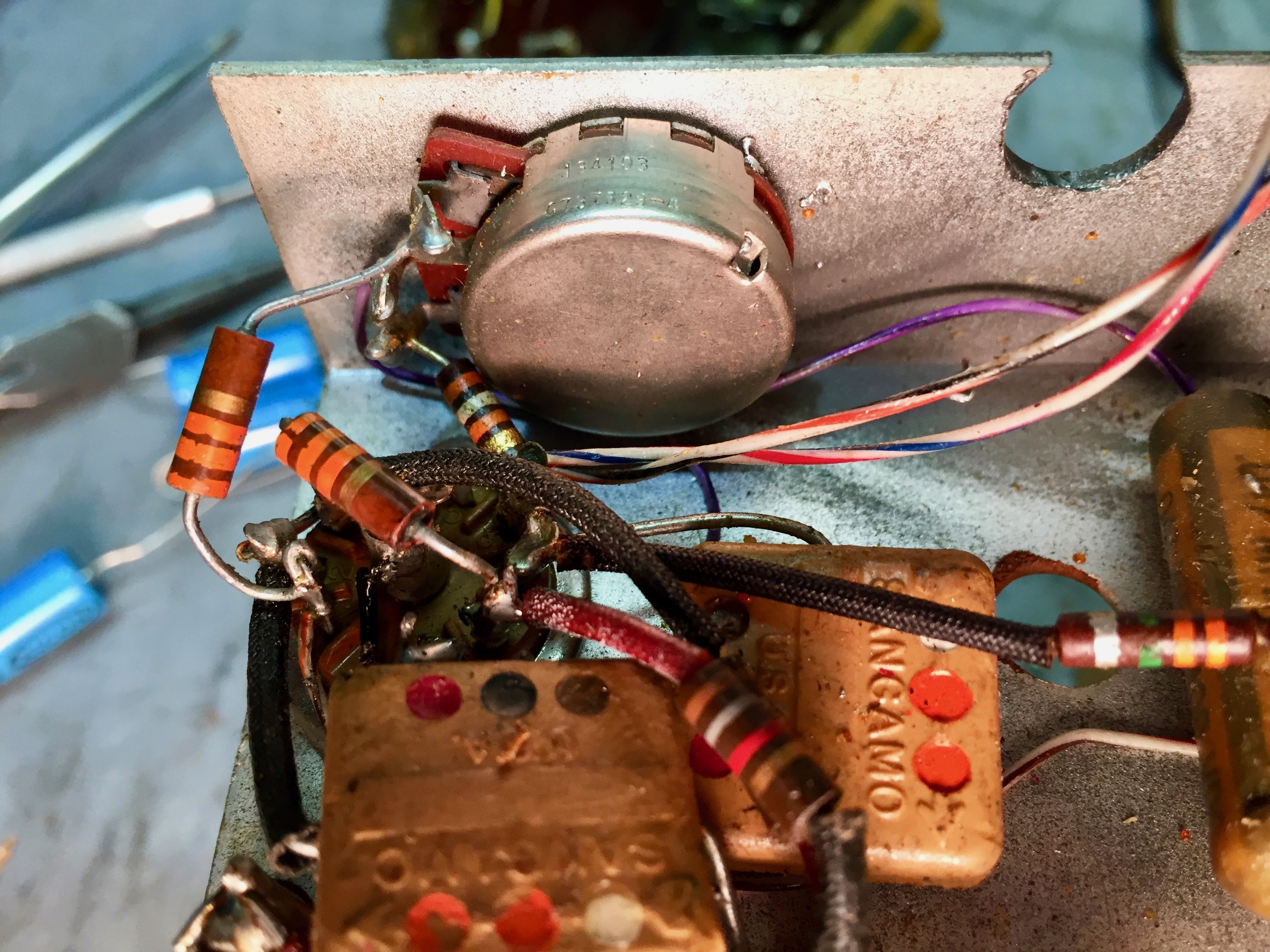
The red and black wires terminate here.
The yellow wire terminates on pin 9 of V3, the 12AU7. That’s the high side of the filament winding.
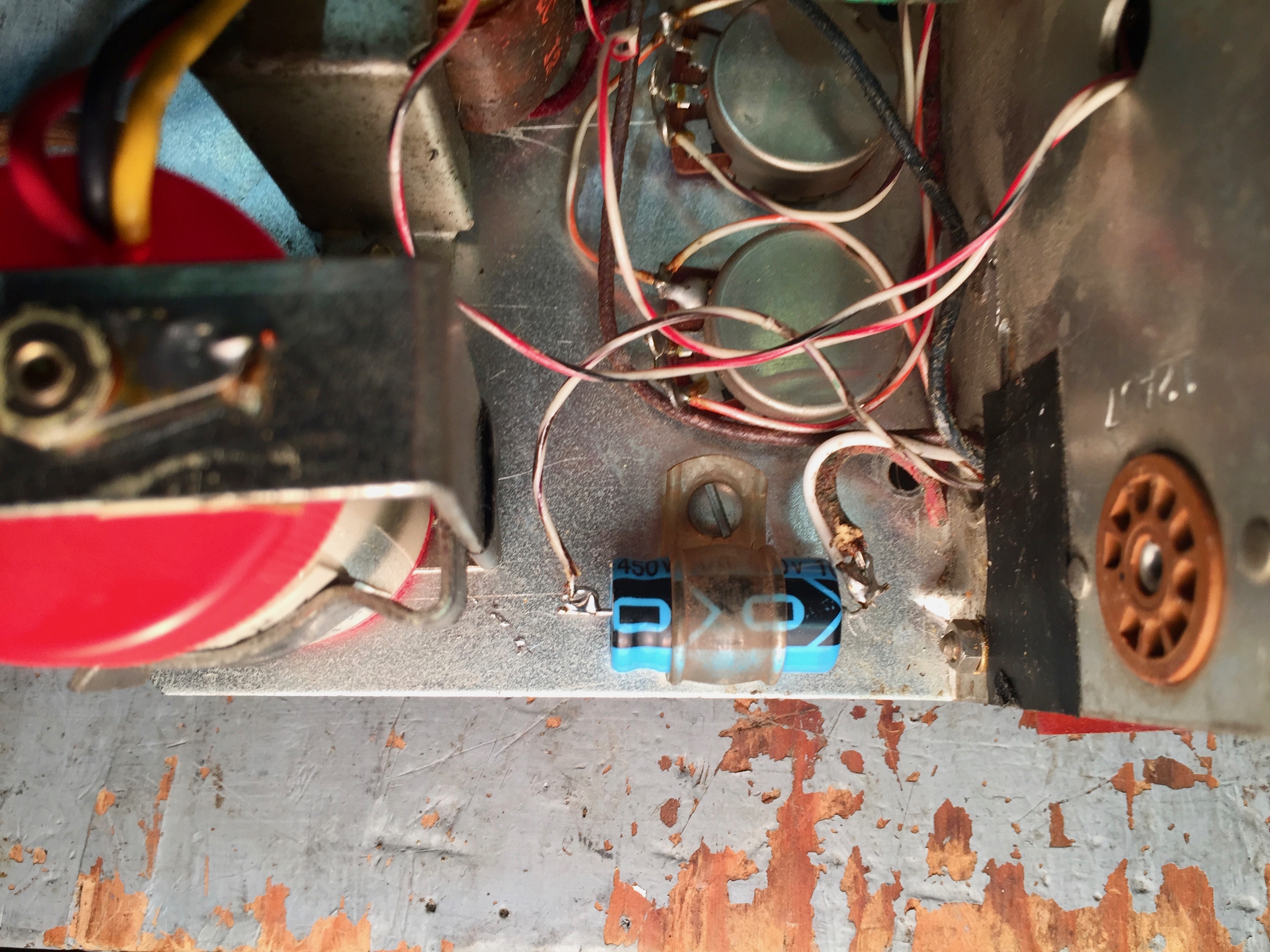
I replaced the electrolytic with a 10 µF 450 volt capacitor. I didn’t have any 10 µF caps in stock with lower working voltages. I didn’t increase the size of the filter capacitor because the WV-97A uses a 6AL5 as the rectifier, and I didn’t want to overstress it.
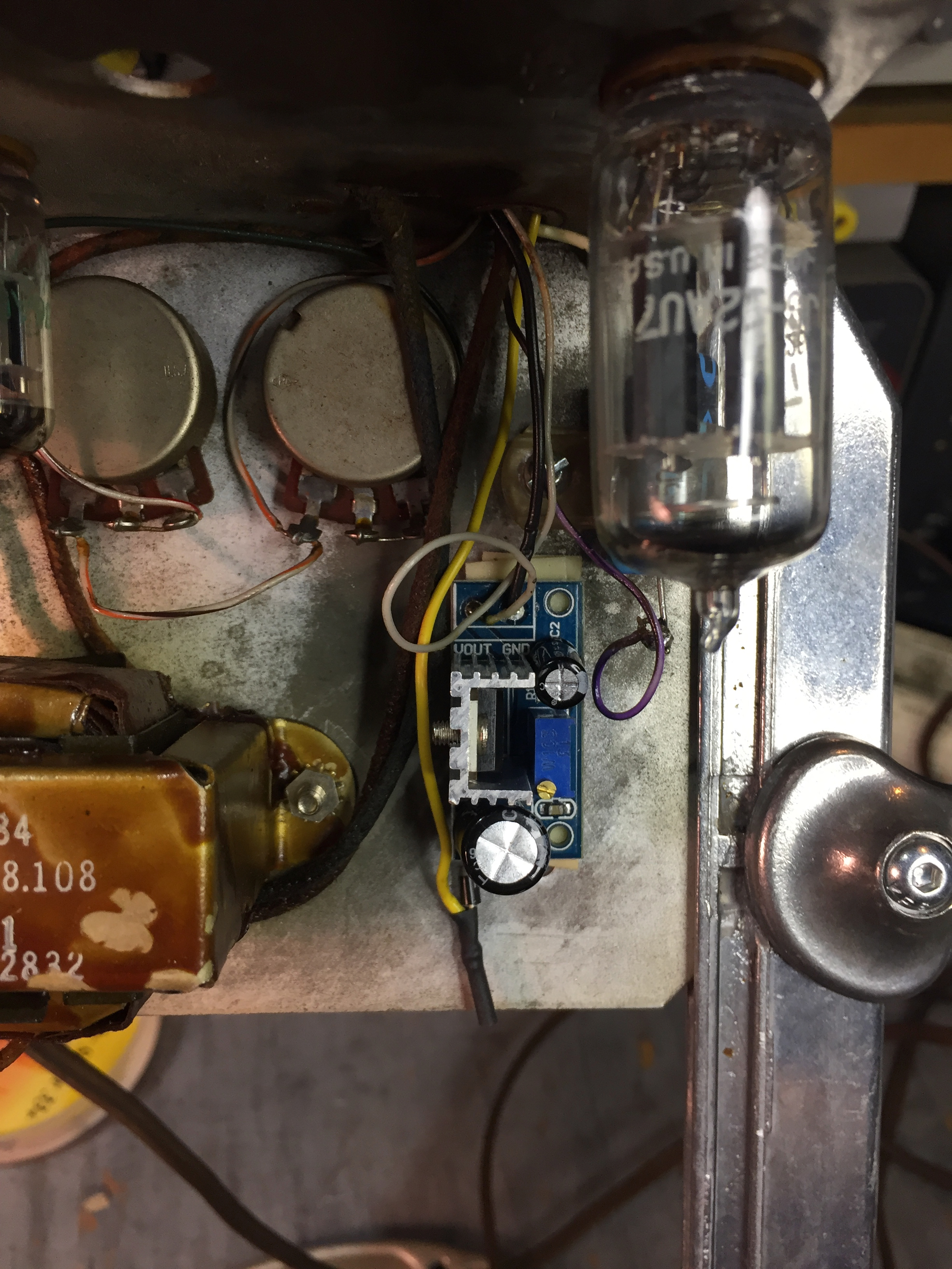
I used a pre-fabbed LM317 regulator board I bought on eBay.
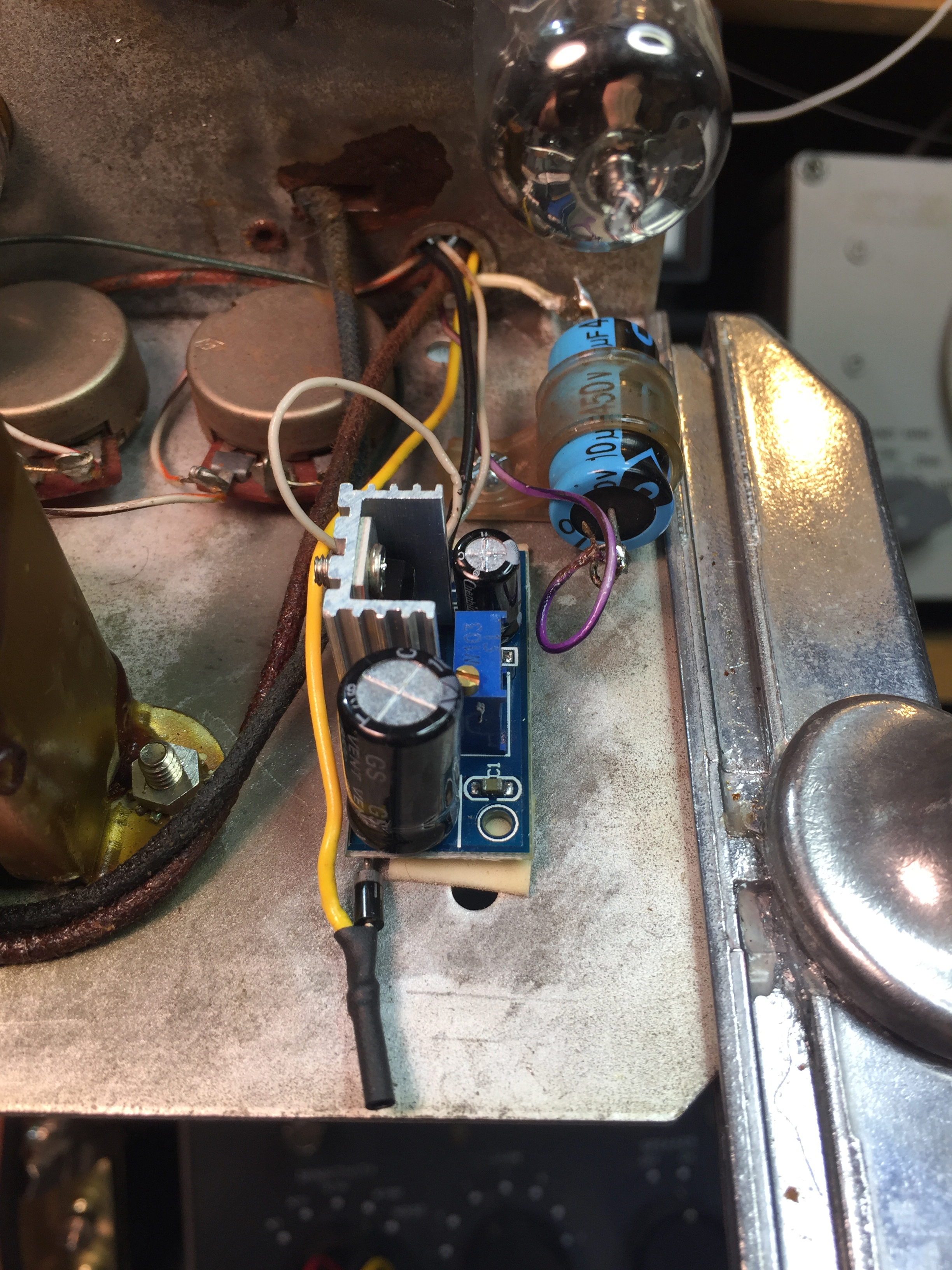
I modify them by removing the input and output terminal strips, soldering in an input filter capacitor and diode, and putting a 51 ohm resistor across the trim-pot. I mounted this one with double-sided tape, because I got the wire just a bit to short to mount it using the old mounting hole (:oops:).
I had to break out the Ungar iron with the #4039 tip to solder the chassis ground connection.
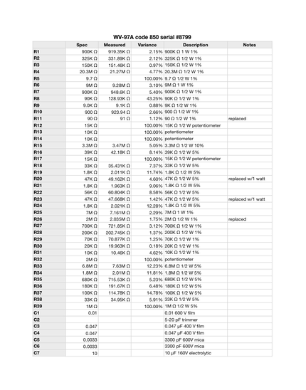
I finally broke down and bought a PC board holder for my Panavise. It turns out to work well for holding the WV-97A chassis.
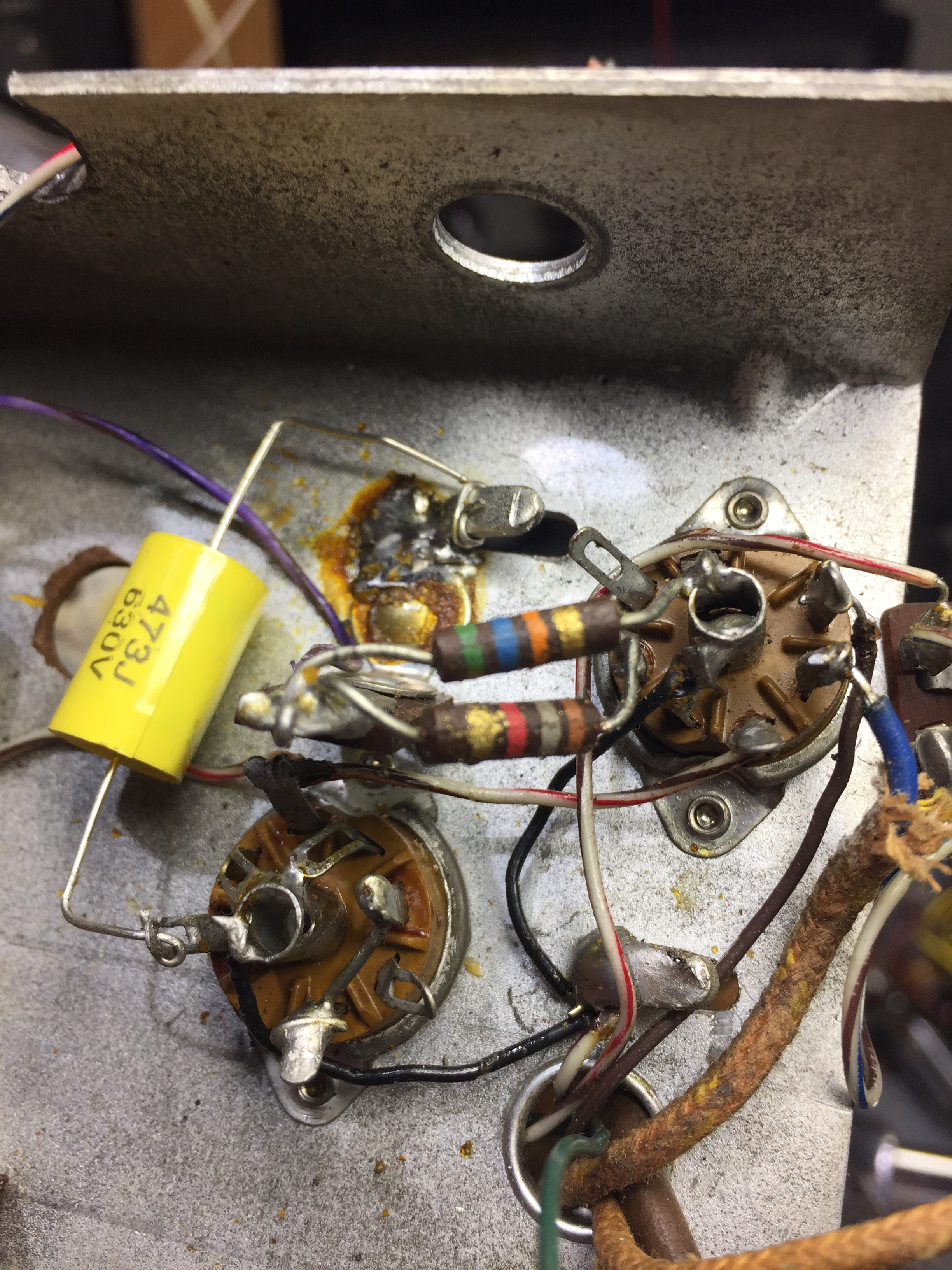
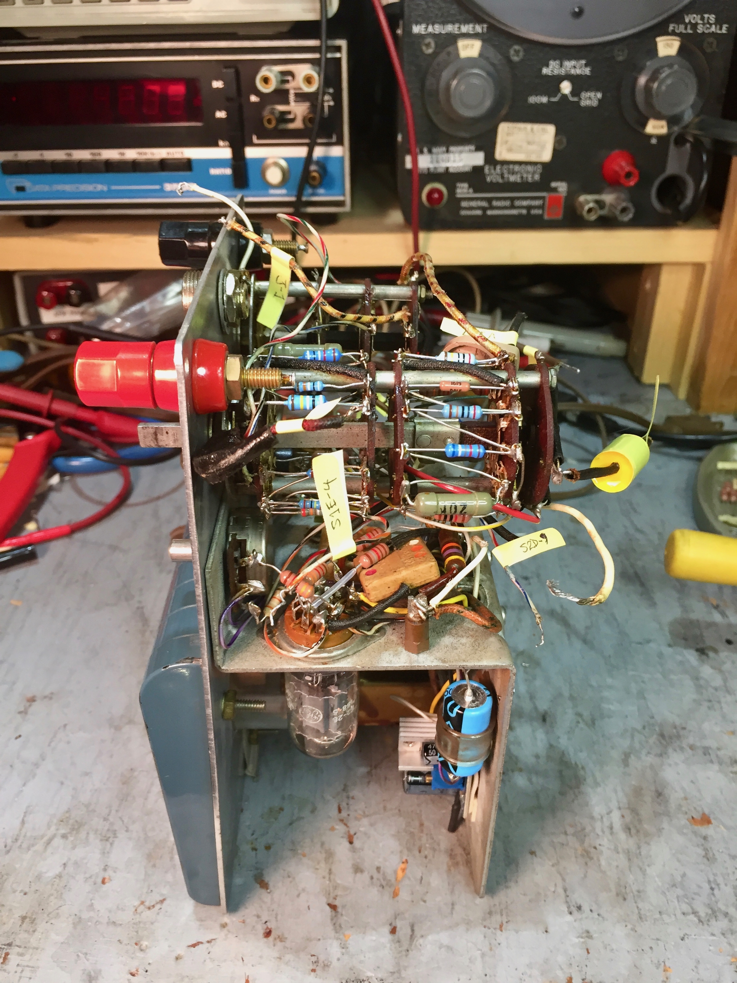
Here I’ve replaced the bad resistors on the chassis. I’ve settled on using Vishay/Dale CCF60 series resistors, when I can get them in the values I need. I buy them from Mouser.
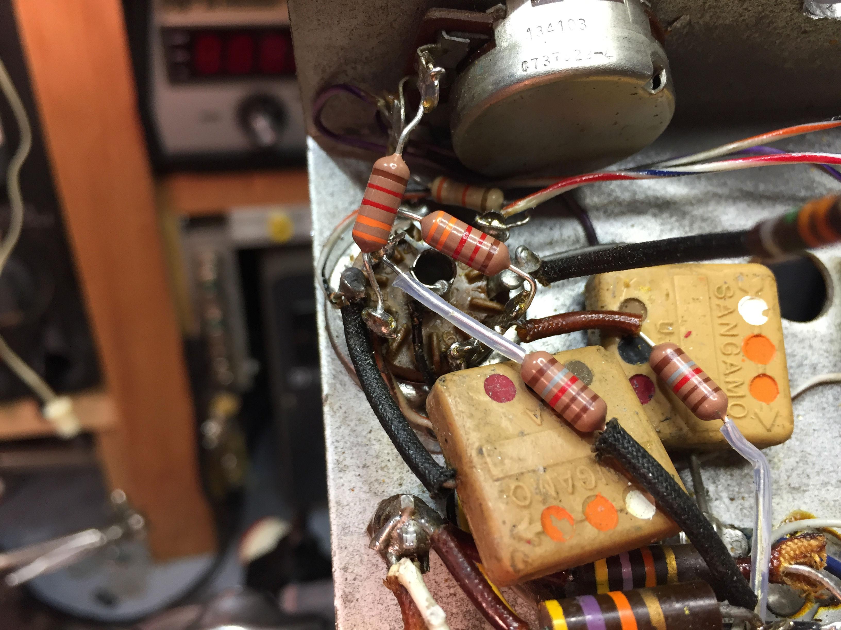
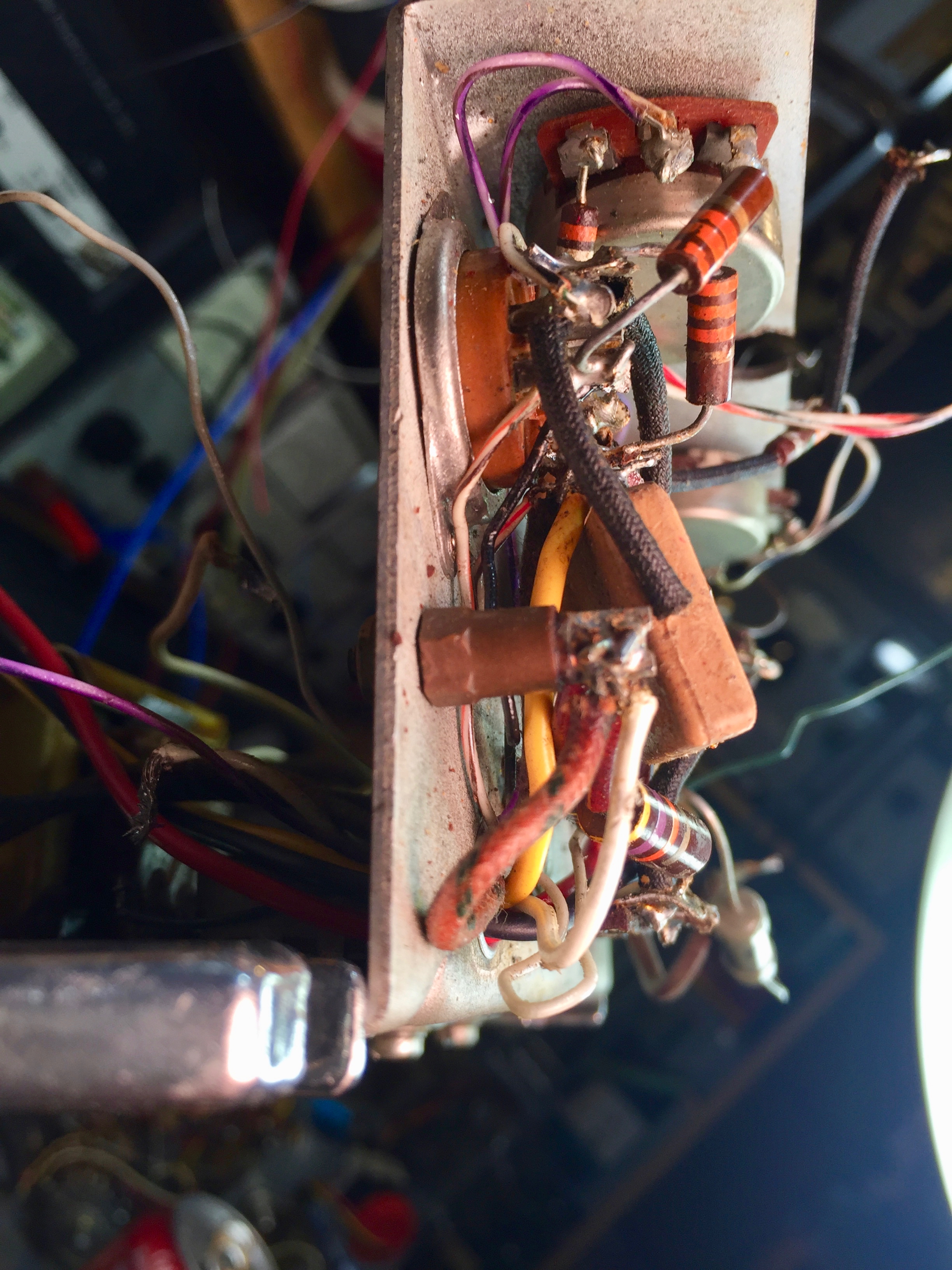
The area around V3 was pretty crowded.
V1 and V2 were roomier.
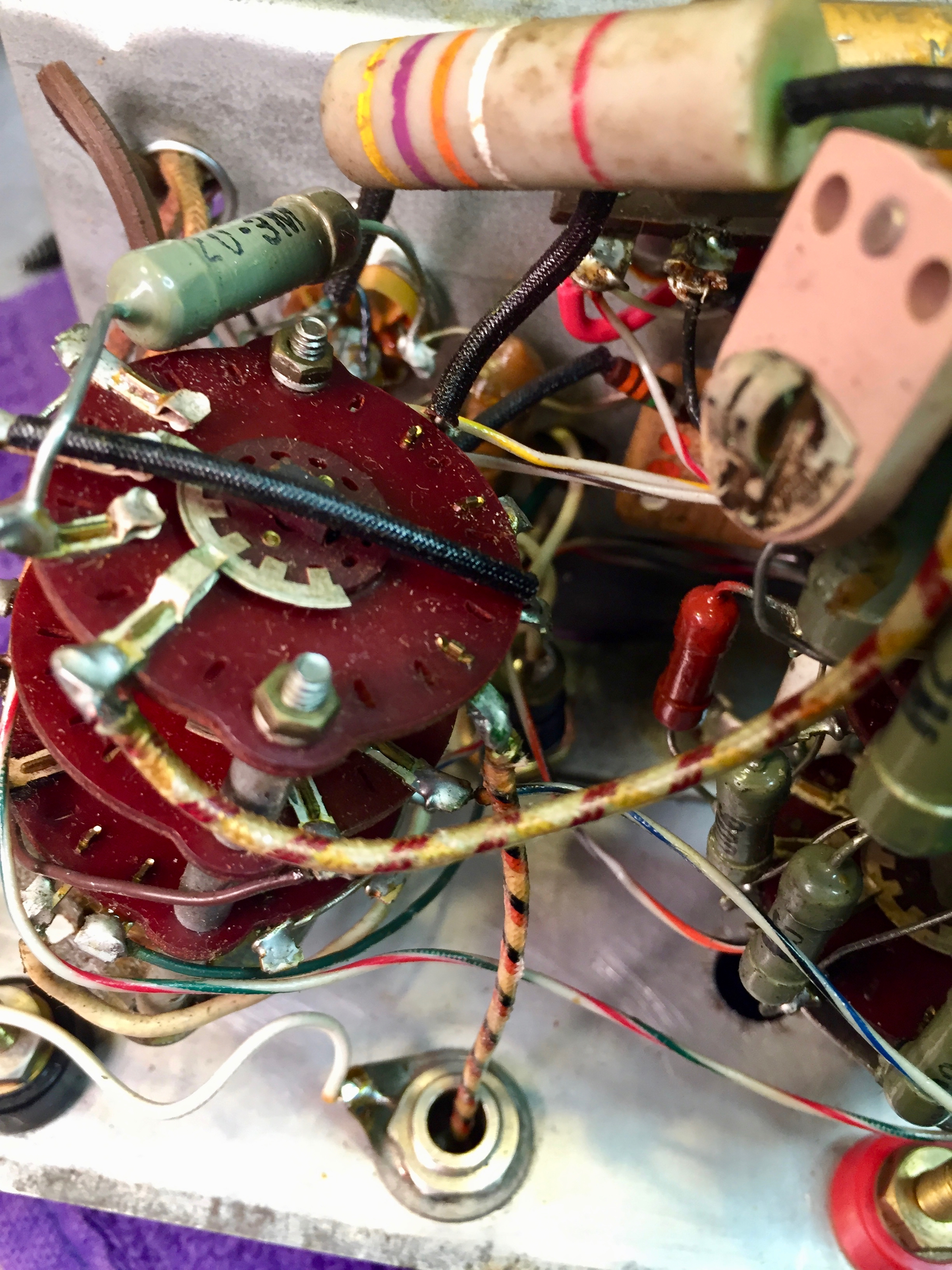
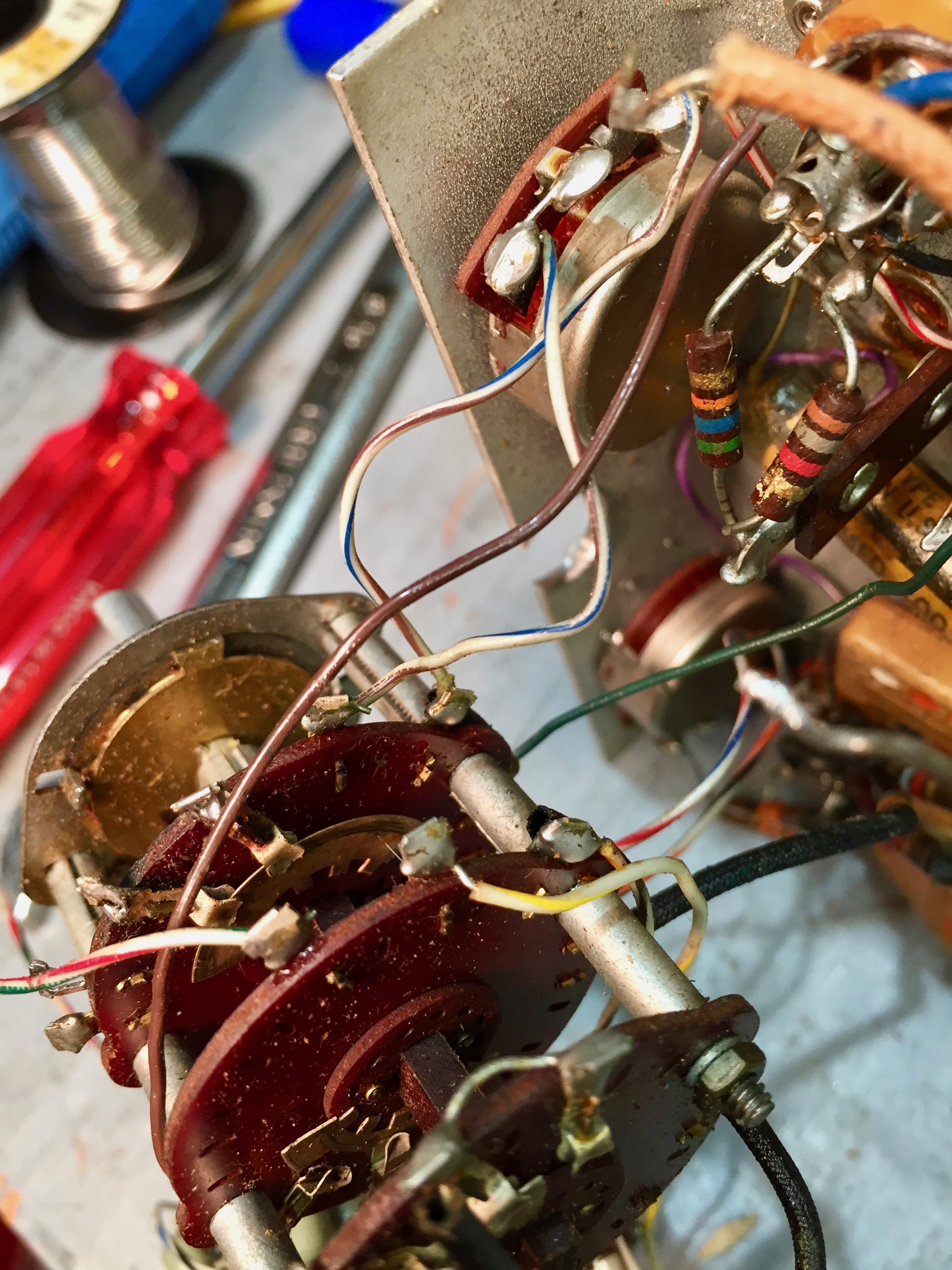
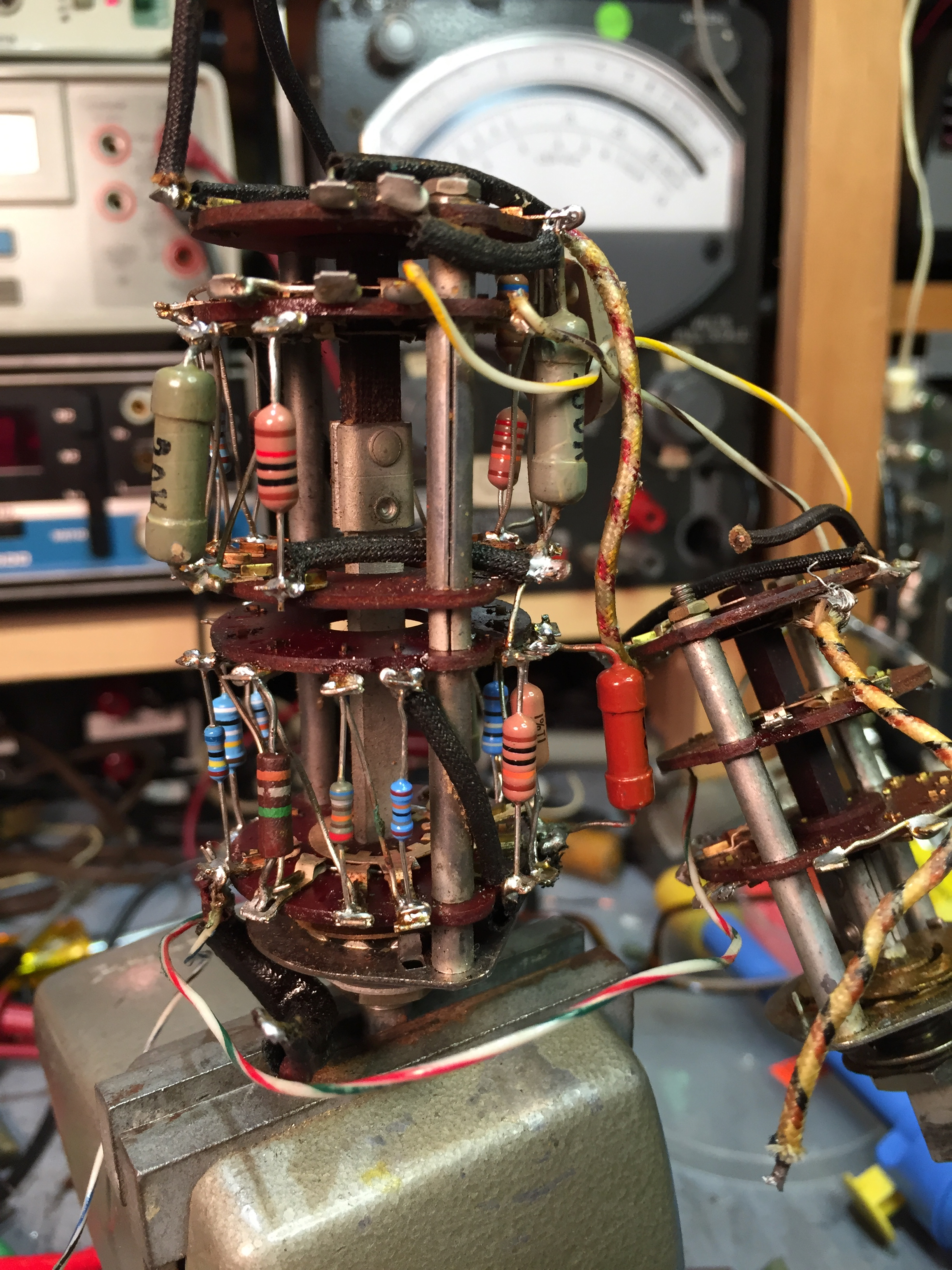
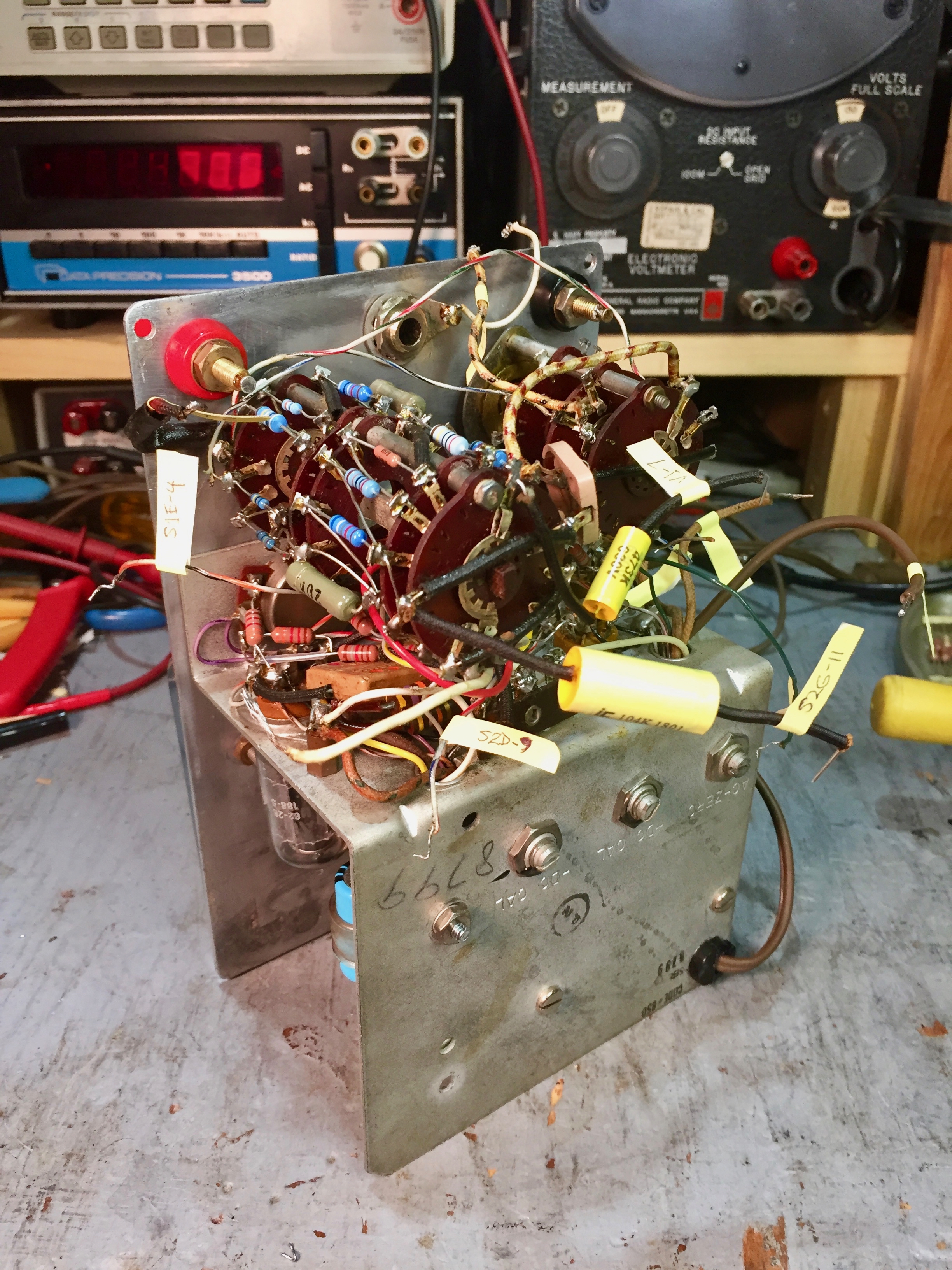
Now comes the big challenge - the range switch.
Most of the precision deposited carbon resistors are out of tolerance. The folklore on ARF says these resistors rarely drift out of tolerance, but not so in this case. My HP 410B had similar problems, though not as bad.
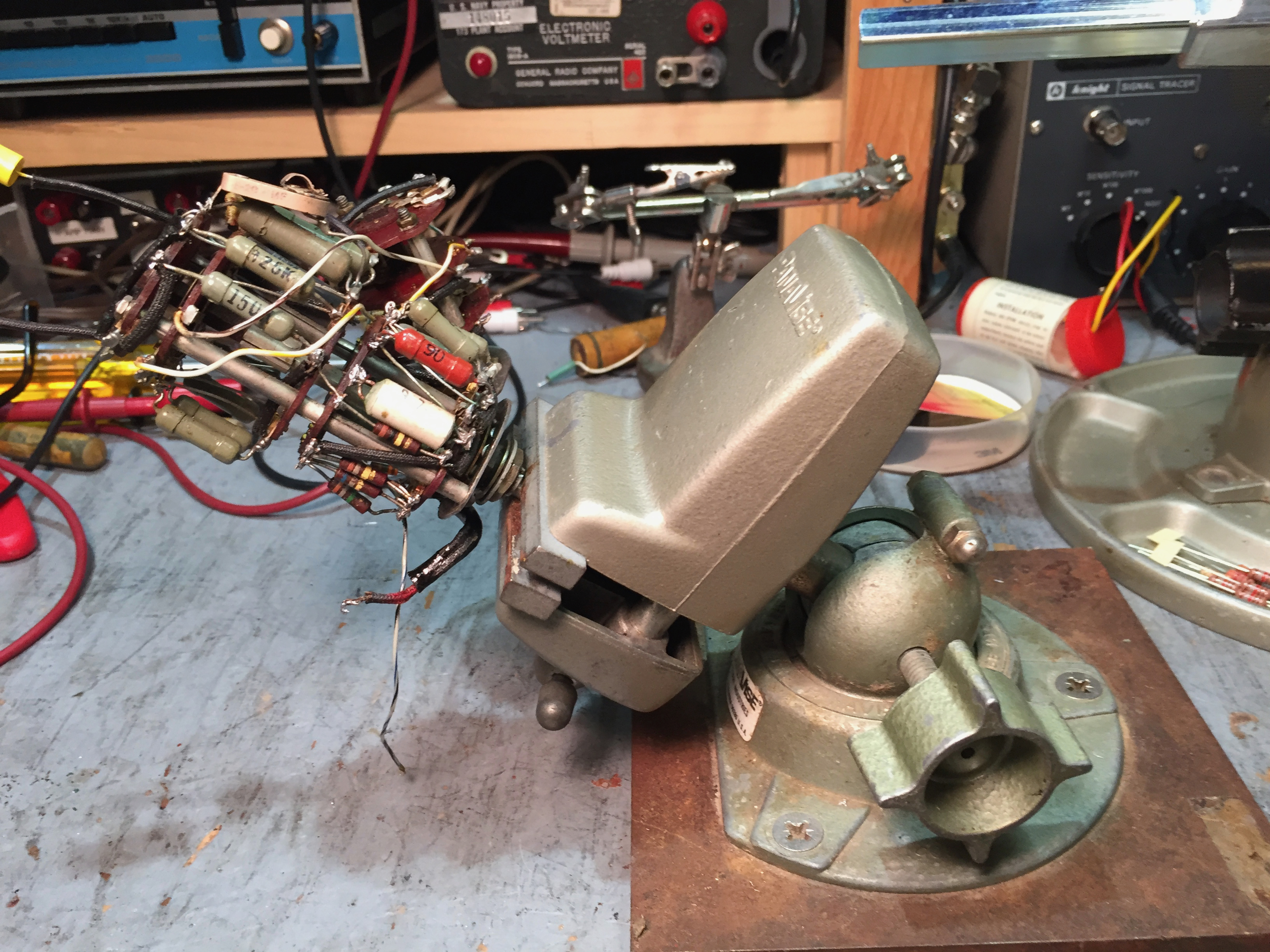
Holding the shaft of the switch in a Panavise is handy for repositioning the switch as you work.
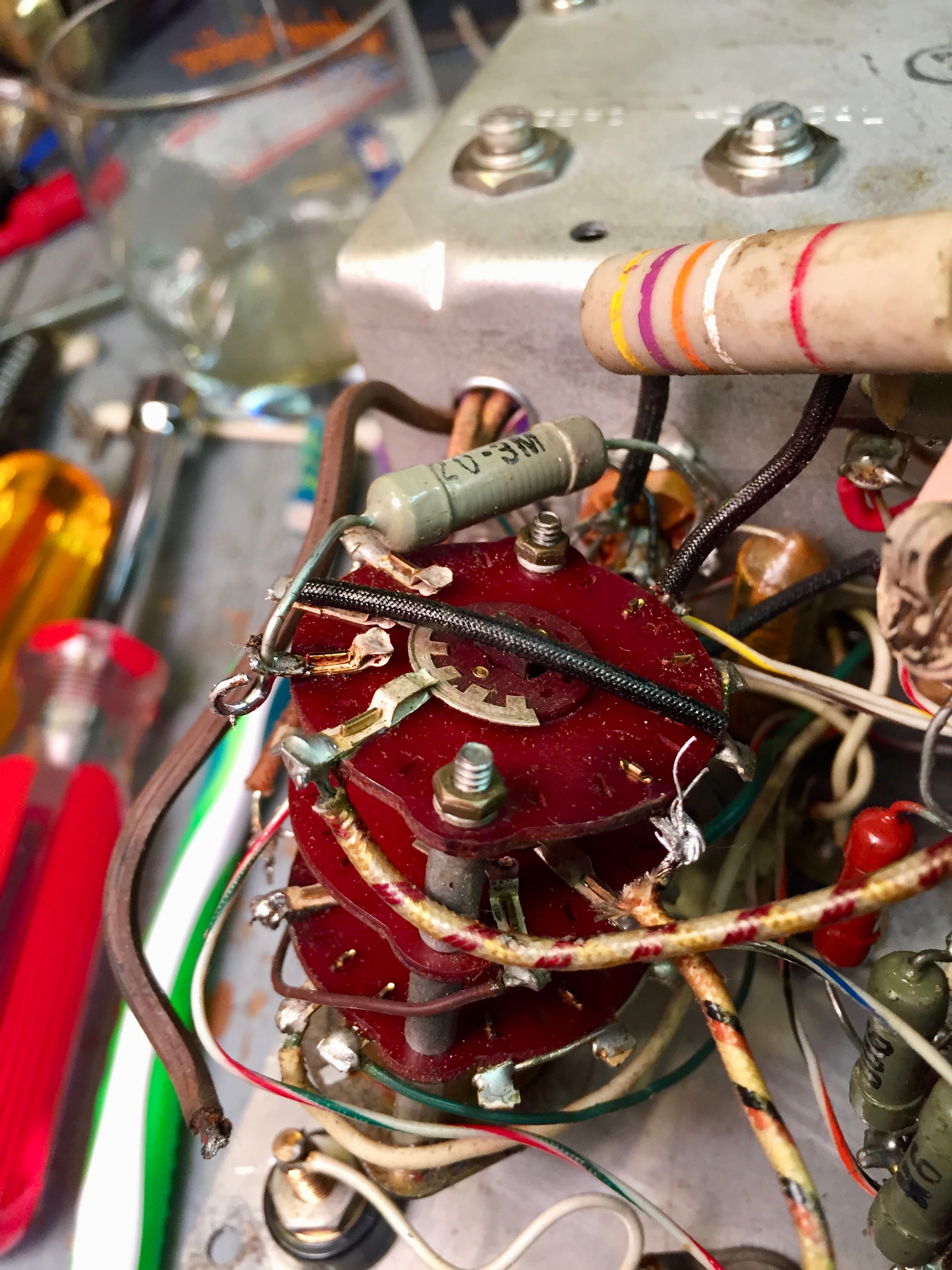
Here I’ve replaced the 7MΩ with a 6.98MΩ resistor and the 2MΩ with a 2.00MΩ resistor.
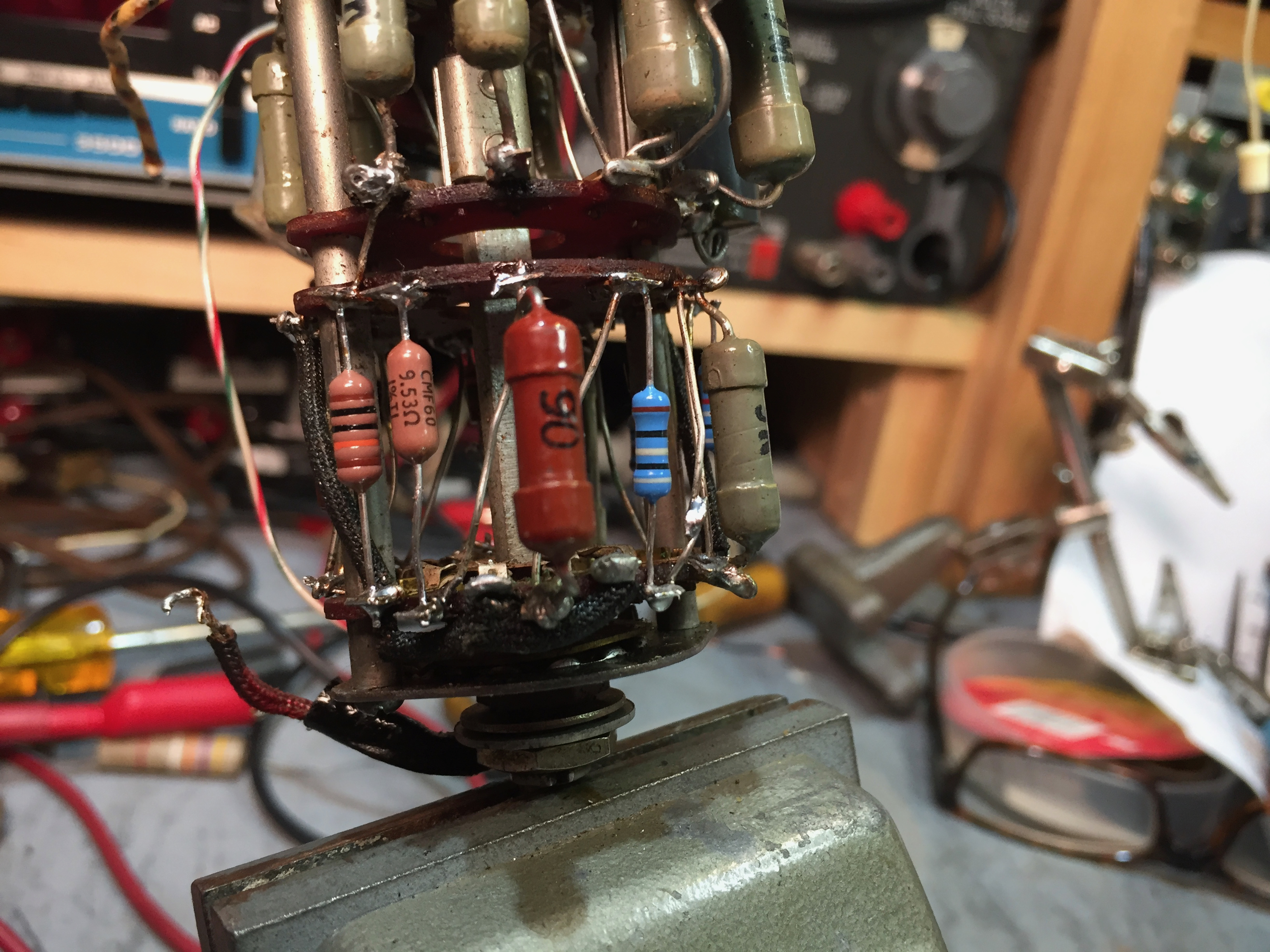
The 90 ohm resistor was close to spec, so I left it in rather than replace it with a 90.9Ω from my stock. This 90Ω resistor had clearly been replaced, since it’s a different style than the other precision resistors and the leads on the replacement weren't wrapped around the terminal, unlike the others.
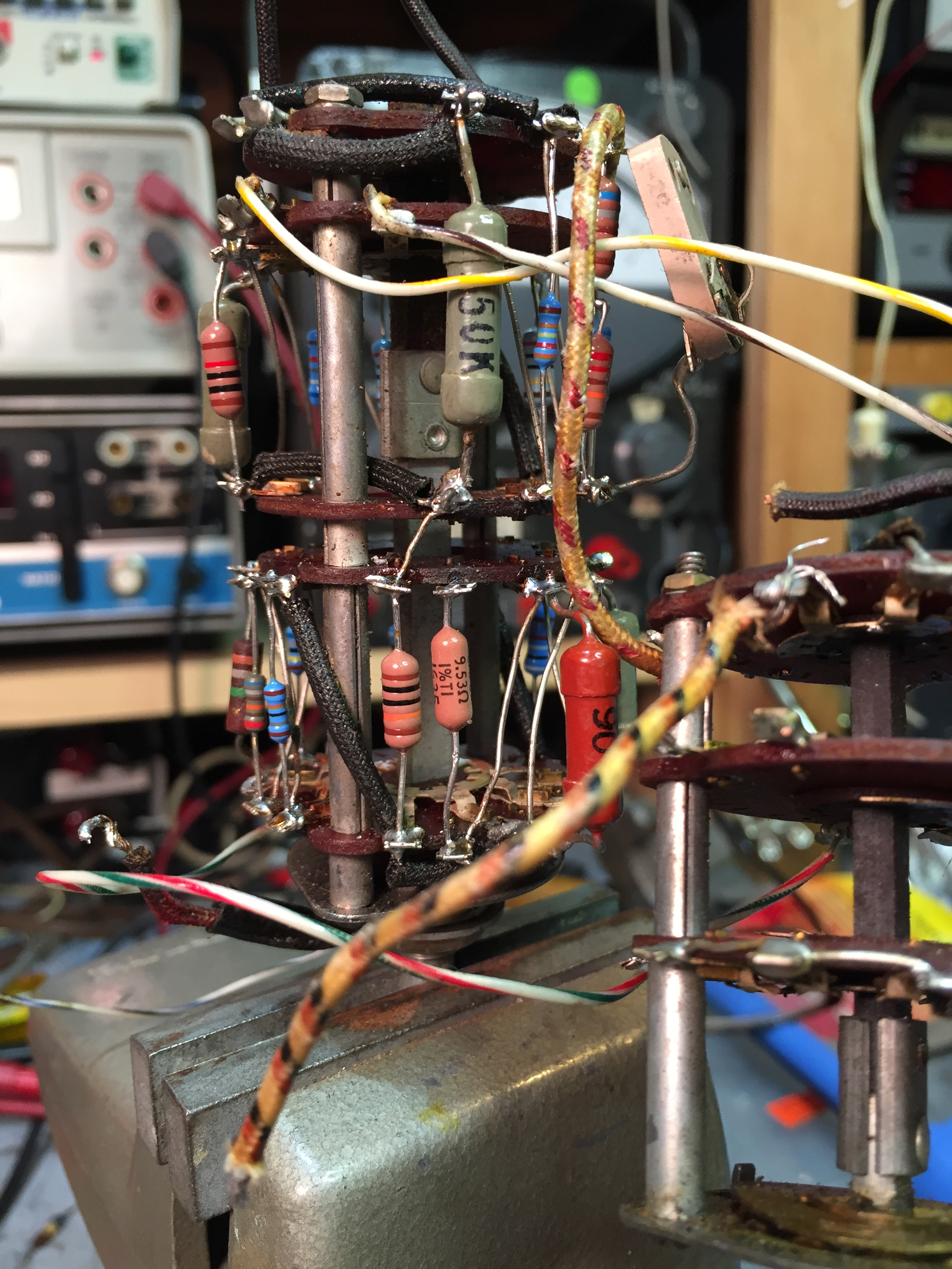
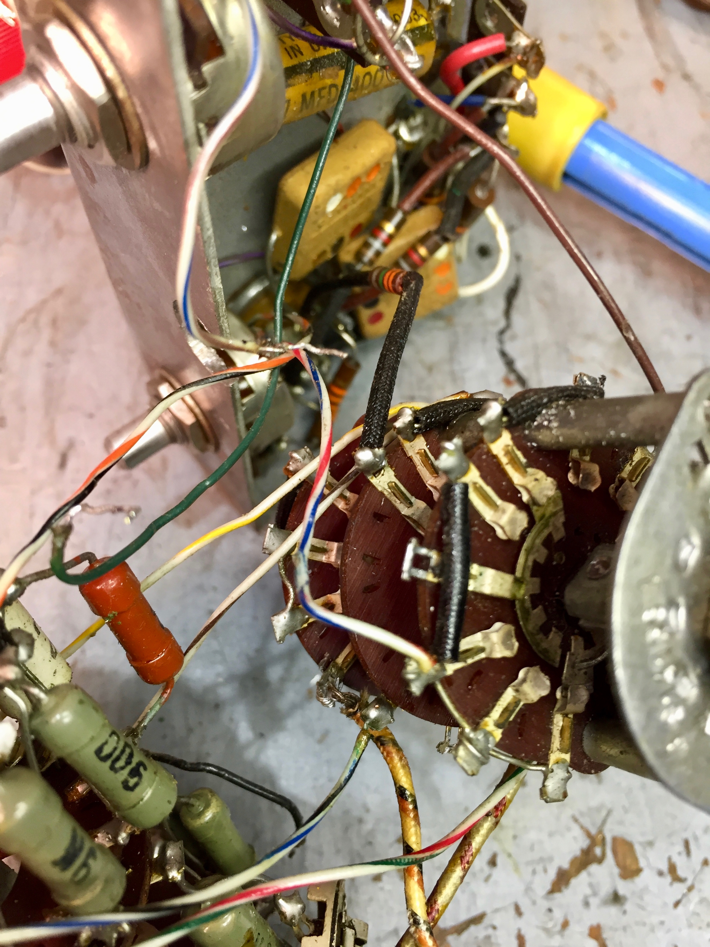
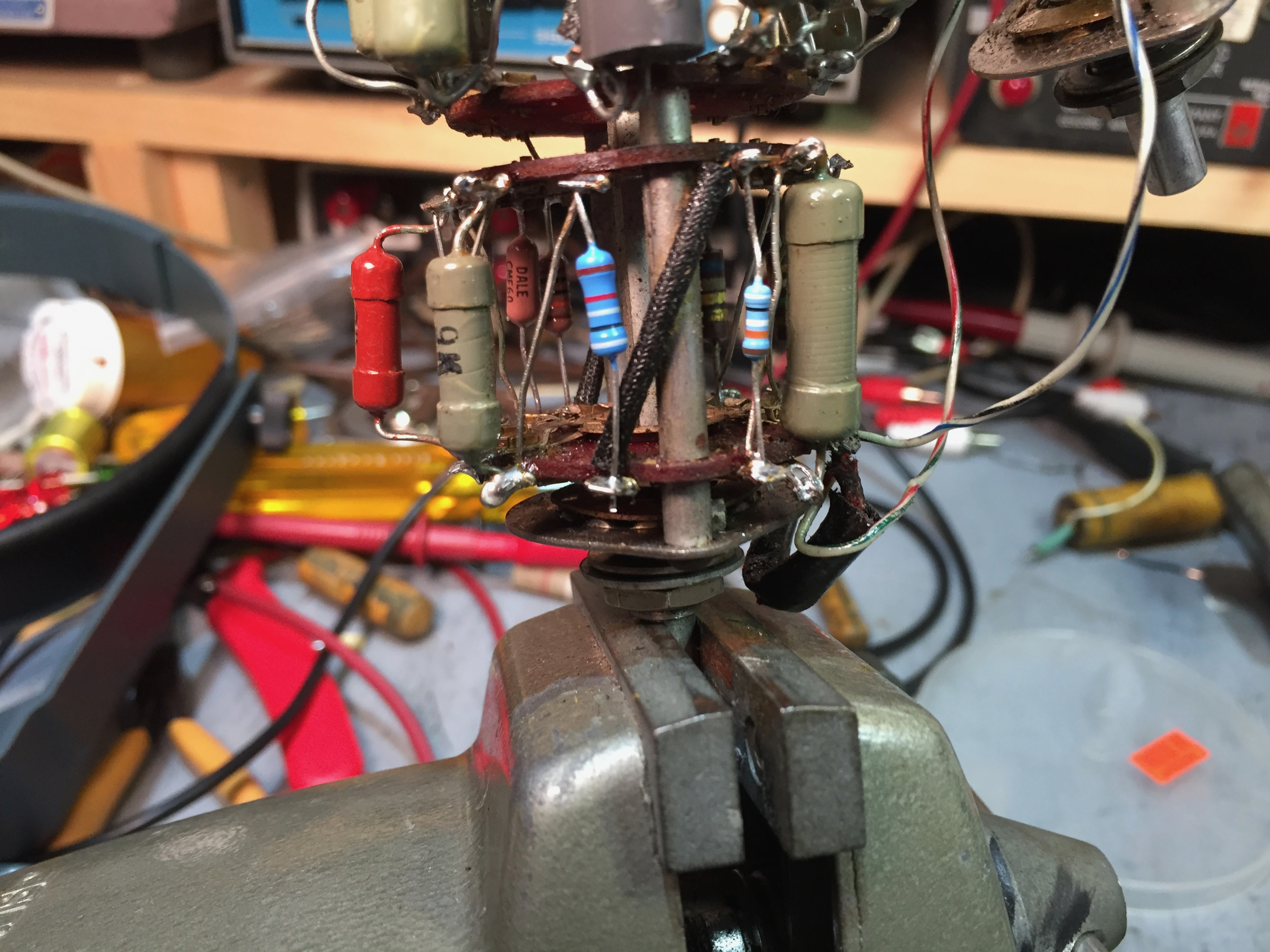
Working on the second deck of the range switch.

The 20KΩ resistor was still in spec, so I left it in place.
I don’t have 1.8 MΩ resistors in stock, and somehow missed ordering them when I ordered stock for this restoration. I’ll have to put in another Mouser order.
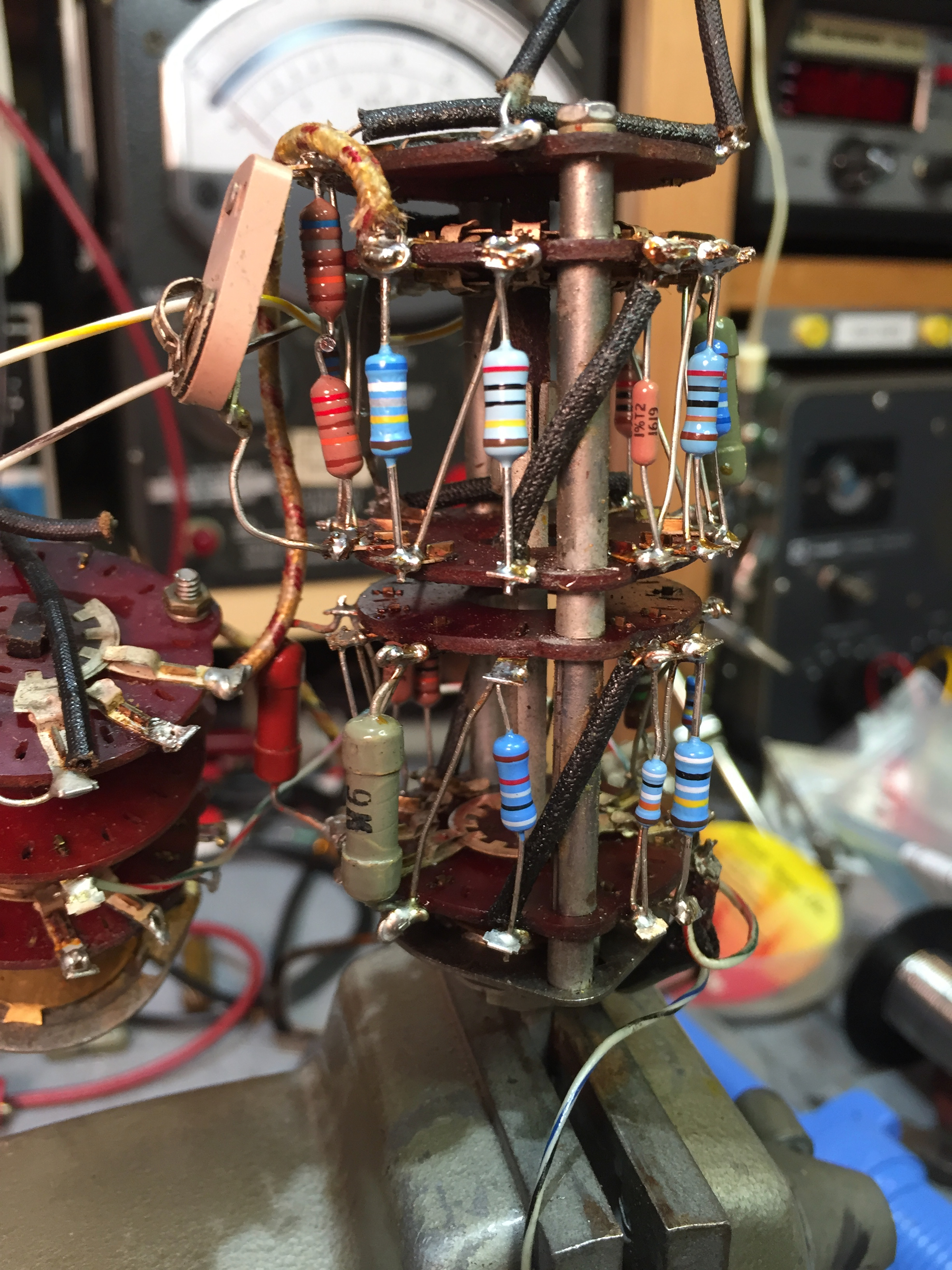
Almost done. The 9KΩ resistor is also still within tolerance.
After I get back home from vacation, I’ll get to tackle the hardest part - putting everything back together!
Update #1
It would have been better to label the wires as I disconnected them.
But it really wasn’t too hard to follow the schematic and label the connections.
It’s starting to look like a VTVM again, now that I’m putting the pieces back together.
Albeit an upside-down VTVM. Setting it right-side-up would risk damaging the range and function switches.
I’ve still got to reconnect everything.
I’m going to wait until I’ve completed reassembling the VTVM and calibrating it before polishing the plastic meter cover. I don’t want to risk scratching it after doing all the work to polish it.
Update #2
I’ve reconnected everything (I hope!).
As I worked on the function switch, double-checking the connection points against the schematic, I noticed that there were a few wires missing. They must have broken off as I worked on the chassis.
I had also forgotten to replace the connection for the ohmmeter voltage supply. It was removed when I pulled out the Lectrocell battery eliminator.
Now it’s time to power it up and see if I got every wire and component back in the right place.
After verifying basic functionality, the next step will be to calibrate it.
I’m collecting materials to fabricate a switched DC/AC probe, the Ohms probe, and the ground clip. After that, it will be time to polish the meter cover and button everything up.
Update #3
I did a rough preliminary calibration to check out the meter. It looks good.
I wanted to set it upright for calibration, so I cut some legs and clamped them on the chassis.
Warming up the VTVM to let things stablize.
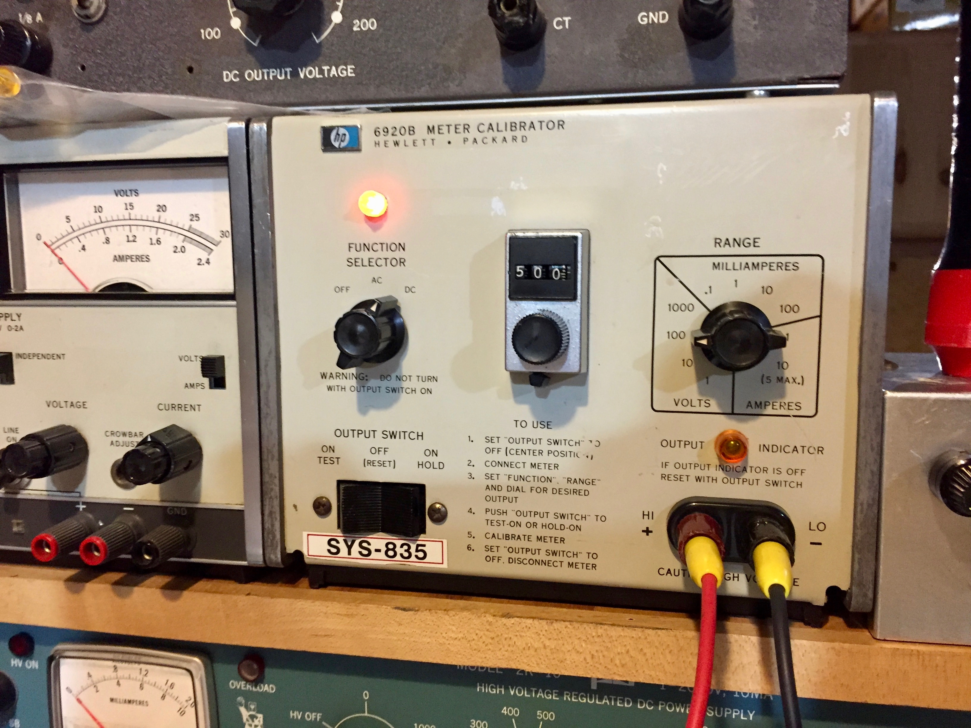
I let the calibrator warm up for a while too.
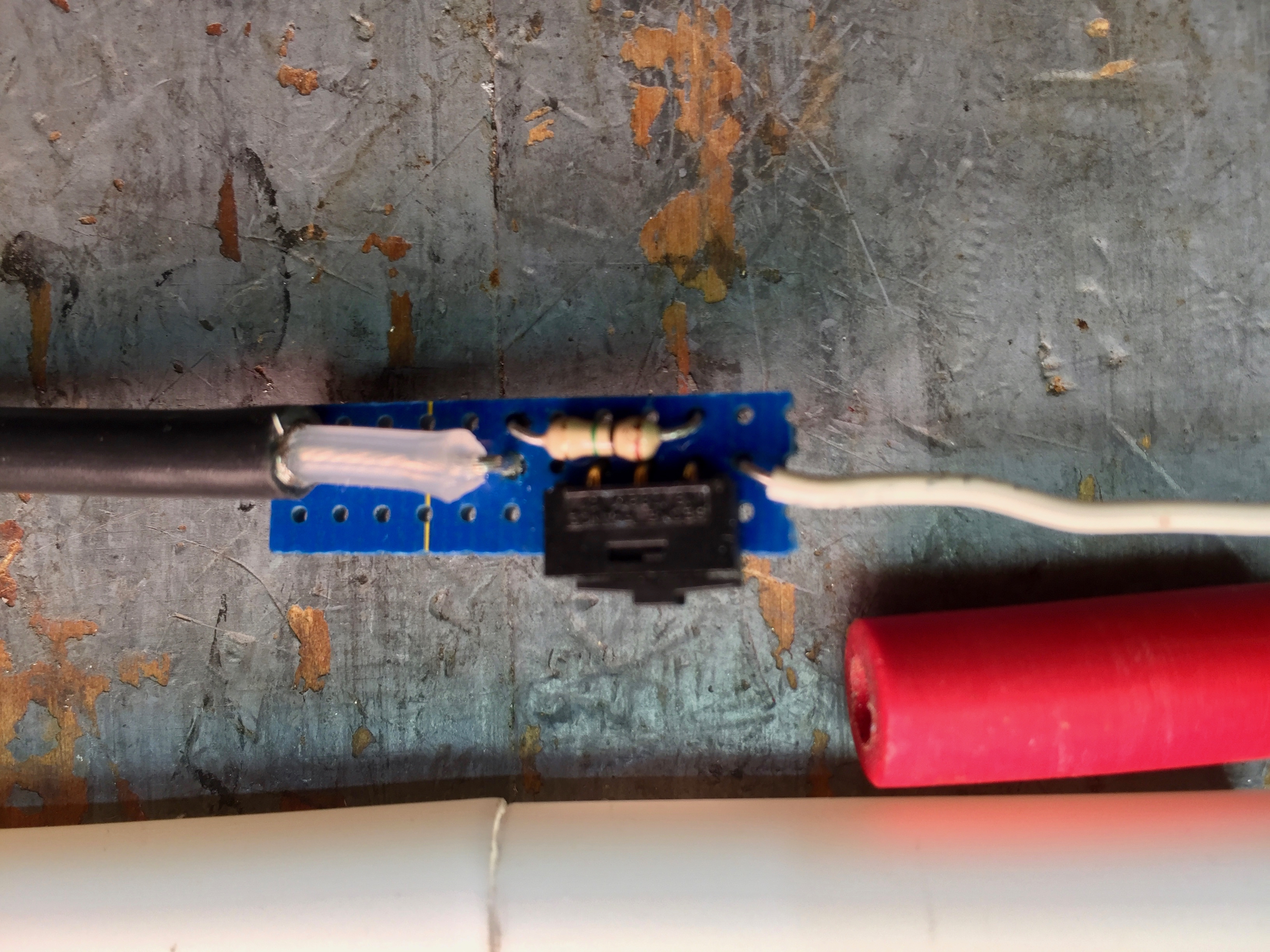
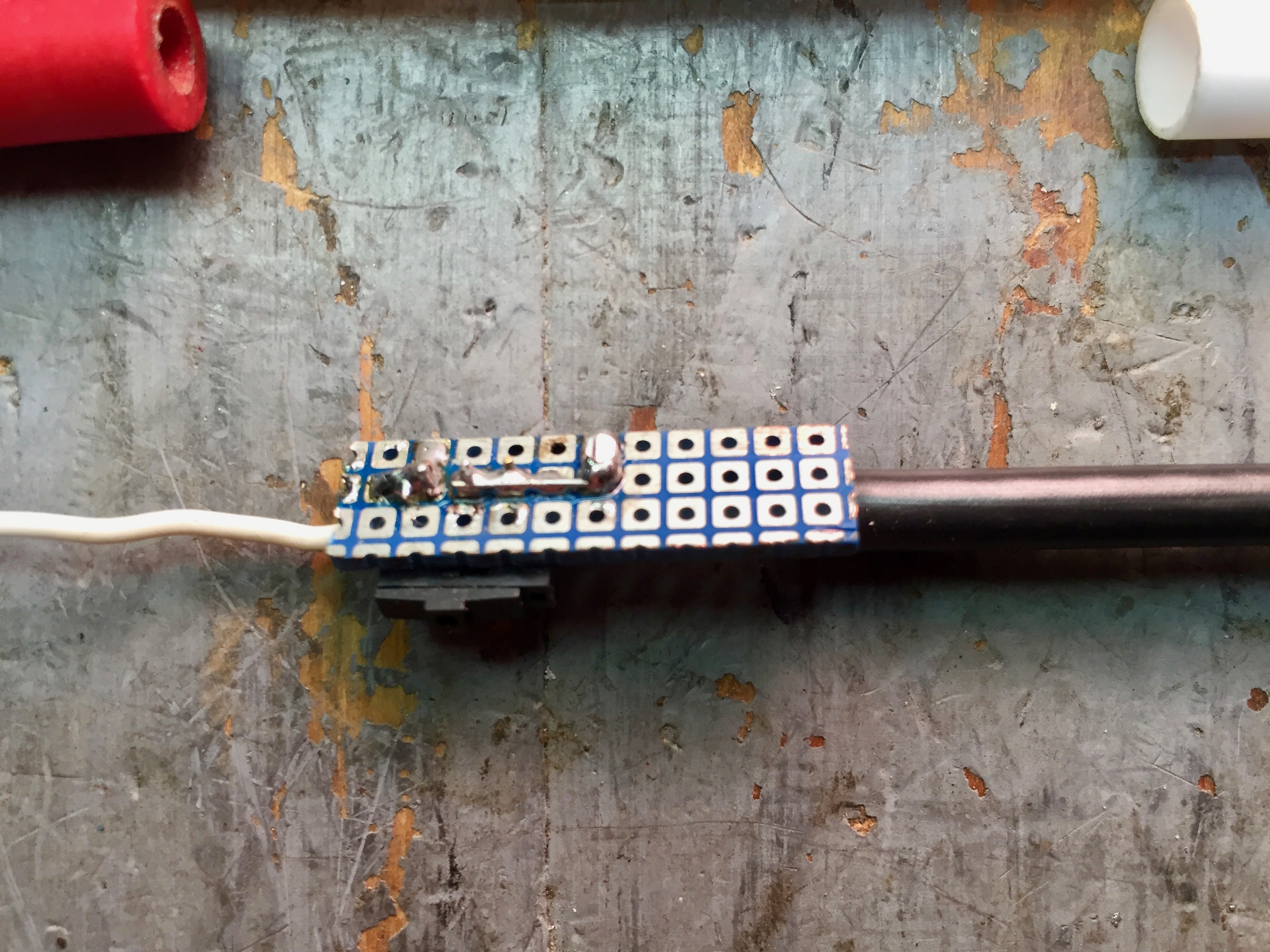
In the meantime, I started building the switchable DC/AC-Ω probe. I used a small slide switch mounted on a piece of pad-per-hole perf-board. Sorry for the fuzzy photo.
The cable is Belden 8259.
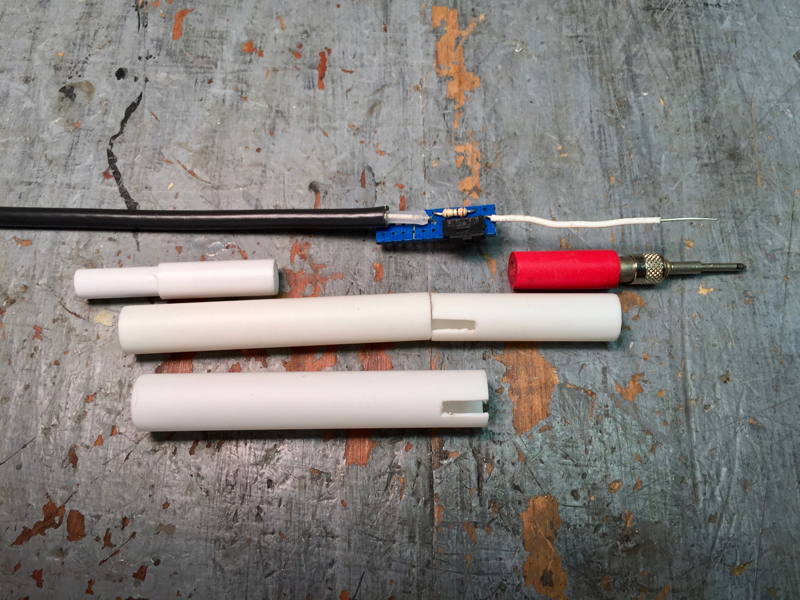
I used telescoping styrene tubing from Evergreen Scale Models to make the probe body. I glued in the phone tip plug to make the probe tip. I should have cut down the body of the phone tip plug to bring the switch closer to the front of the probe. I’ll know better next time.
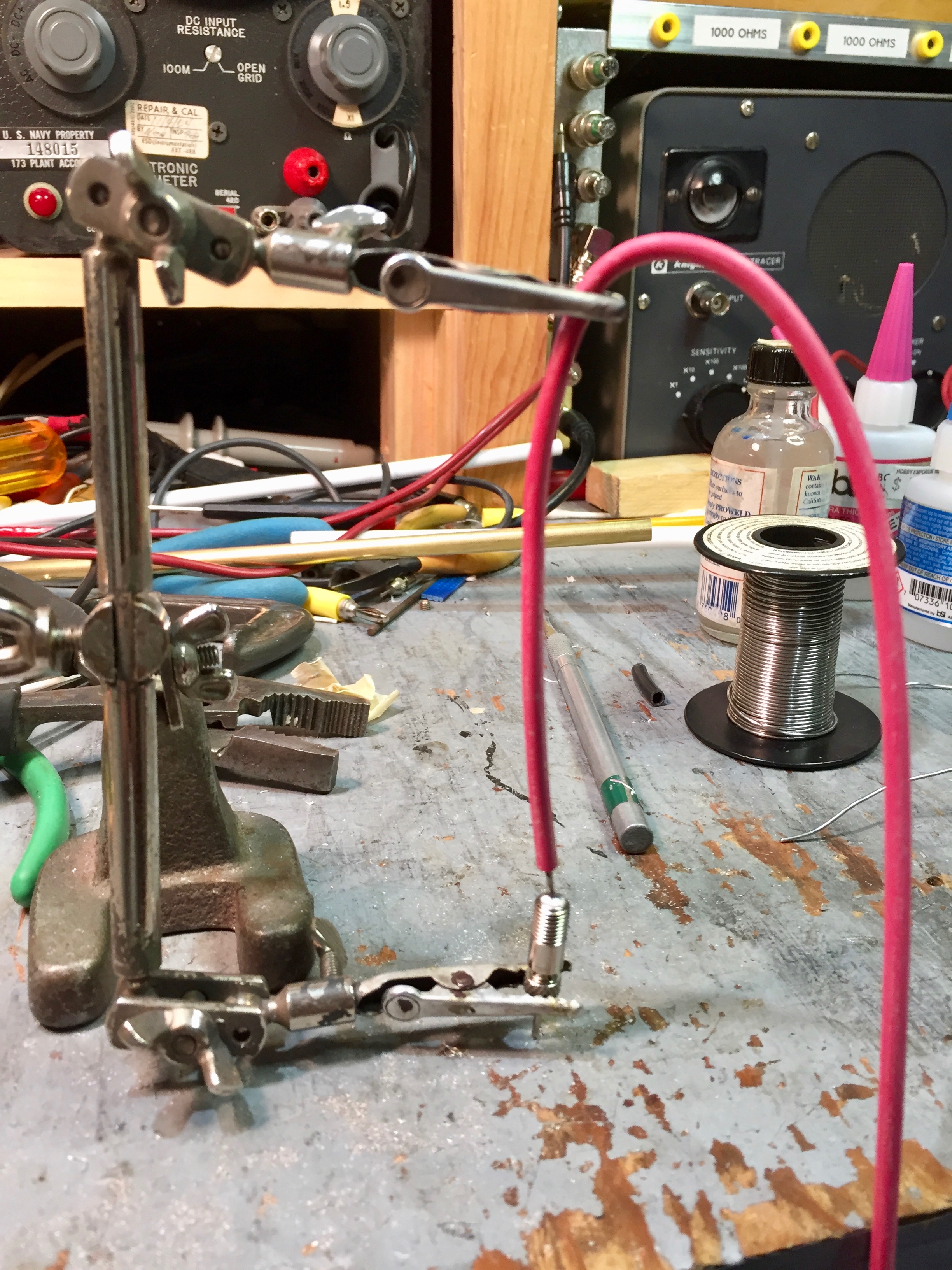
The third-hand tool came in handy for soldering the Ohms probe tip to the test lead.
Here are the assembled probes.
I still need to put some labels on the switchable DC/AC-Ω probe.
I’m letting it warm up now to do the final calibration. After that, I need to polish the meter face and then it’s done.
Update #4
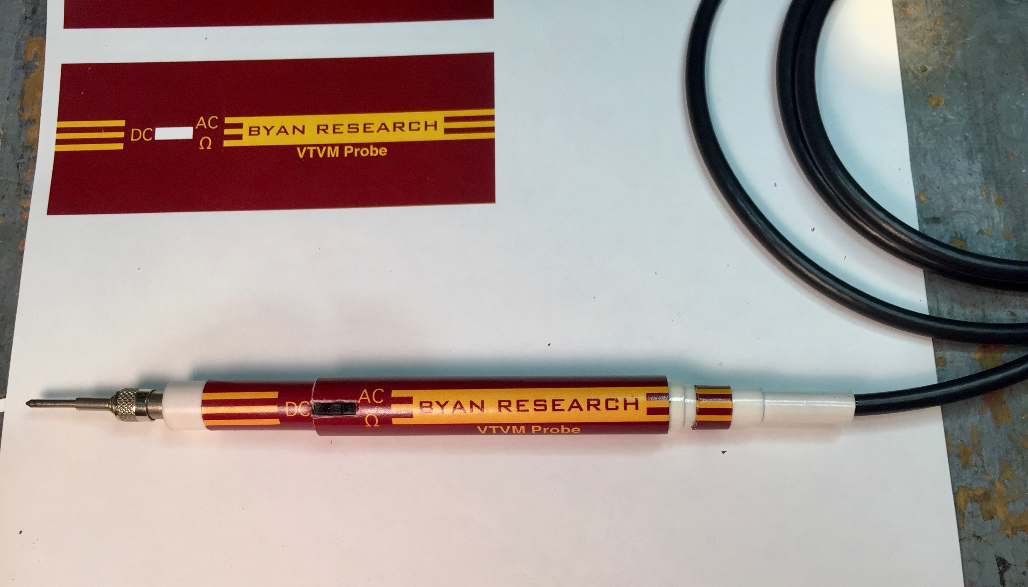
I put some labels on the probe. I had been repairing an RCA switchable probe for the WV-98A while I was building this probe, so I had “AC-Ω” in my mind and labeled the probe that way, although the WV-97A doesn’t use the switchable probe for Ohms. Oh well.
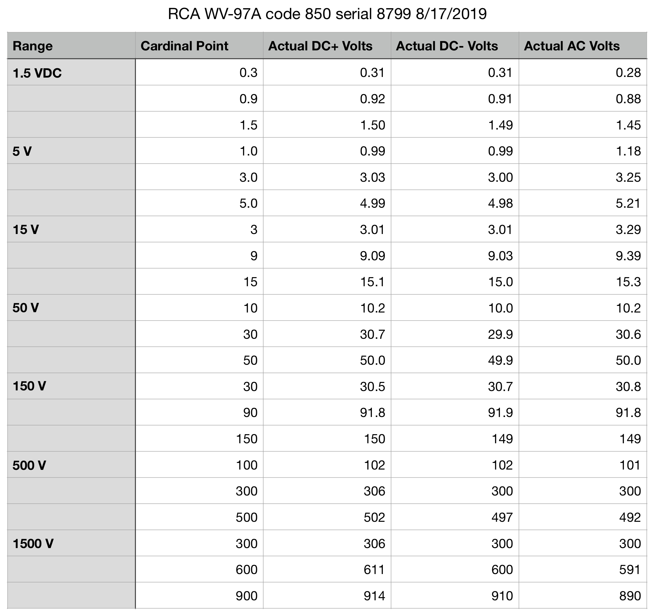
I calibrated the WV-97A up to 900 volts. The 1000 volt cardinal point is over 1000 volts and that’s higher than I can measure accurately. But 900 volts and below are all within spec for the WV-97A.
I thought it would be clever to mask the paint on the meter bezels while I used Novus plastic polish on the meter face. Without masking, I thought the Novus would likely remove some of the paint.
The masking worked fine on the meter from another WV-97A, but on this one, the paint lifted when I removed the masking tape. Uh-oh. Sorry, John.
All that’s left is to pack it up and ship it to John.