

After warming up on my IM-28 restoration, I went on to do my IM-13.
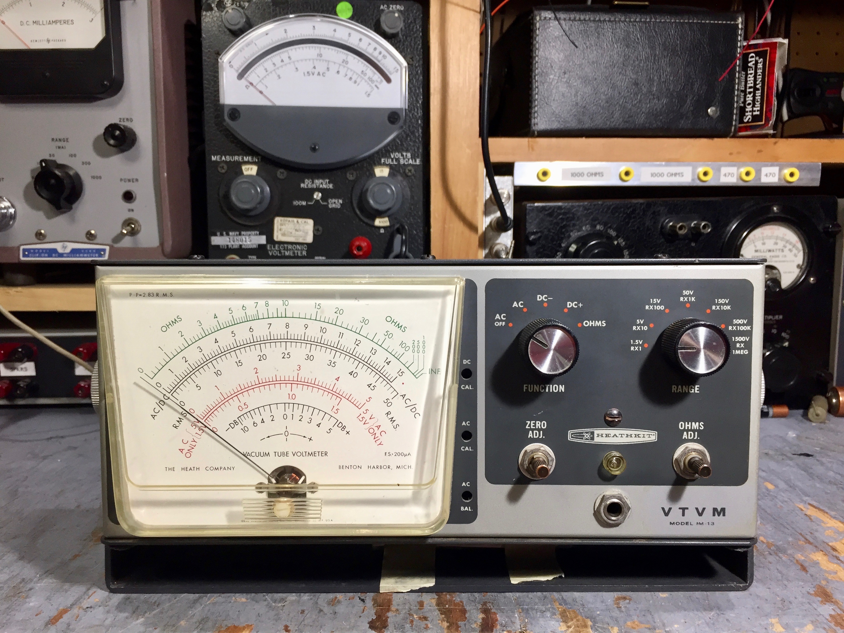
I don’t have a “before” picture, but the cosmetics were pretty much the same as this “after” photo.

One difference is that I swapped meters with the IM-28, as the red scale on the IM-13 had faded.

I want to keep the IM-13 as part of my Heathkit Classic II style collection. I planned to sell off the IM-28, and did so at the fall NEARC meet in Brookline.

I came pretty close to completely re-kitting it.

I didn’t pull the tube sockets or the calibration pots, and I left a few of the old components that were good.

Compared to the IM-28, more of the range resistors on the IM-13 had drifted out of tolerance. That’s not surprising, as the IM-13 could be a decade older than the IM-28.

I replaced the electrolytic, of course, but the original silicon diode was fine.

Some of the five 22 MΩ resistors had drifted out of tolerance, but only two of them, R6 and R7, are actually critical to the calibration of the meter. I replaced those with 1% metal film resistors, and re-used the best of the remaining carbon composition resistors.

The high-ohmage 1% metal films are somewhat expensive, so I didn’t want to deplete my stock unnecessarily.

I replaced a fair number of the range resistors.

I also re-soldered most of the joints. The original builder was a bit stingy with the solder.

While the range switch was out and easily accessible, I applied a bit of DeOxit D100 to the contacts and worked the switch to clean any corrosion from the contact fingers.

I cleaned the old grease from the ball-bearing detent mechanism and re-greased it.

I finished by putting a drop of Mobile One 5W-20 oil on the shaft bearing.

I removed all the wiring from the function switch, ...

… and gave the contacts and mechanism the same treatment as for the range switch.

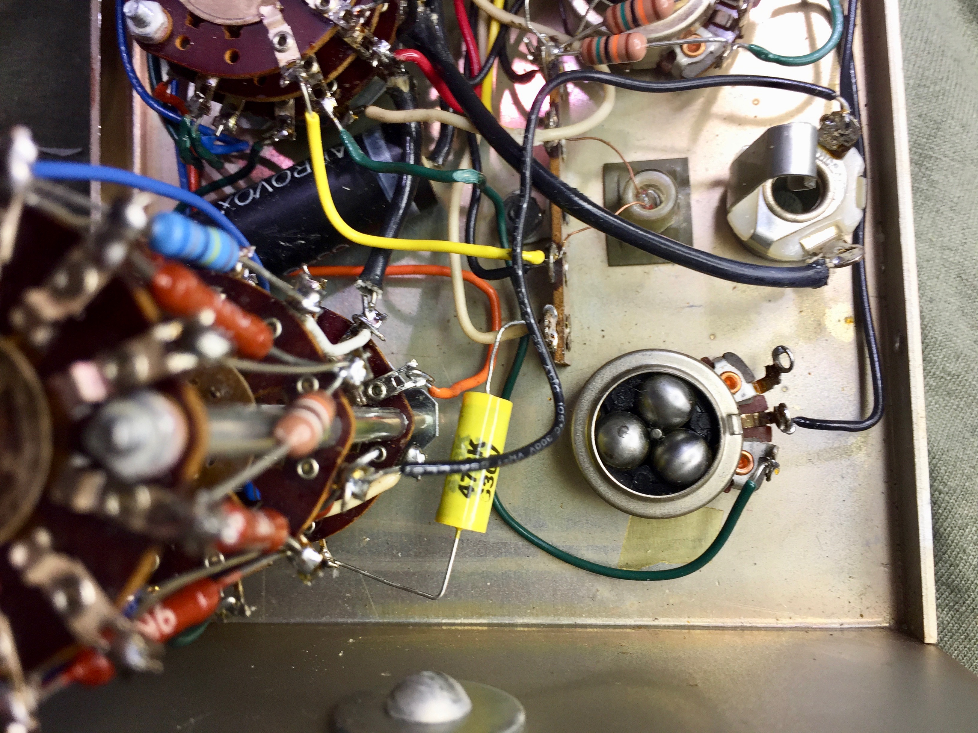
Here I’ve started the re-assembly and re-wiring. The Aerovox 0.047 µF 1600V capacitor tested at 100 GΩ insulation resistance at 500 volts on my GR 1864-B, so I’m re-using it.

In some places I re-used the old wire, but it had tended to work-harden between its initial installation and my removal and re-installation. I had trouble with the wire breaking when I tried to re-wrap it on the terminals.

So, as I moved along with the reconstruction, I started using new wire. Fortunately I have a high quality scan of the full assembly manual for the IM-13, obtained before DataPro chased most of the full manual scans off the net.

The manual specifies the length for each wire in the kit. This saves some time when re-assembling and helps keep the lead dress neat.


A few more steps further along the way.


I should have followed the instructions and installed all the wires on the tube chassis before bolting it to the front panel. It was a bit challenging to make some of the connections with everything in the way.


I removed the D cell battery holder, as I plan to replace it with a line-powered regulated power supply. I ran the wire for the power feed to the resistance range section, but left the battery end unconnected, until the time that I install the power supply.

I haven’t populated the boards yet, but you can see that the power supply is about the same size as the original D cell battery holder in the IM-13.
Update:

The battery eliminator PCB mounts on three 1/4 inch long 6-32 threaded standoffs. Two of the standoffs take the place of the mounting screws for the original battery holder. I had to drill a hole for the third.

It would have been a lot easier to drill and mount the board if I had removed the chassis from the front panel.

Next time I’ll have the boards on-hand to install the battery eliminator earlier in the restoration.
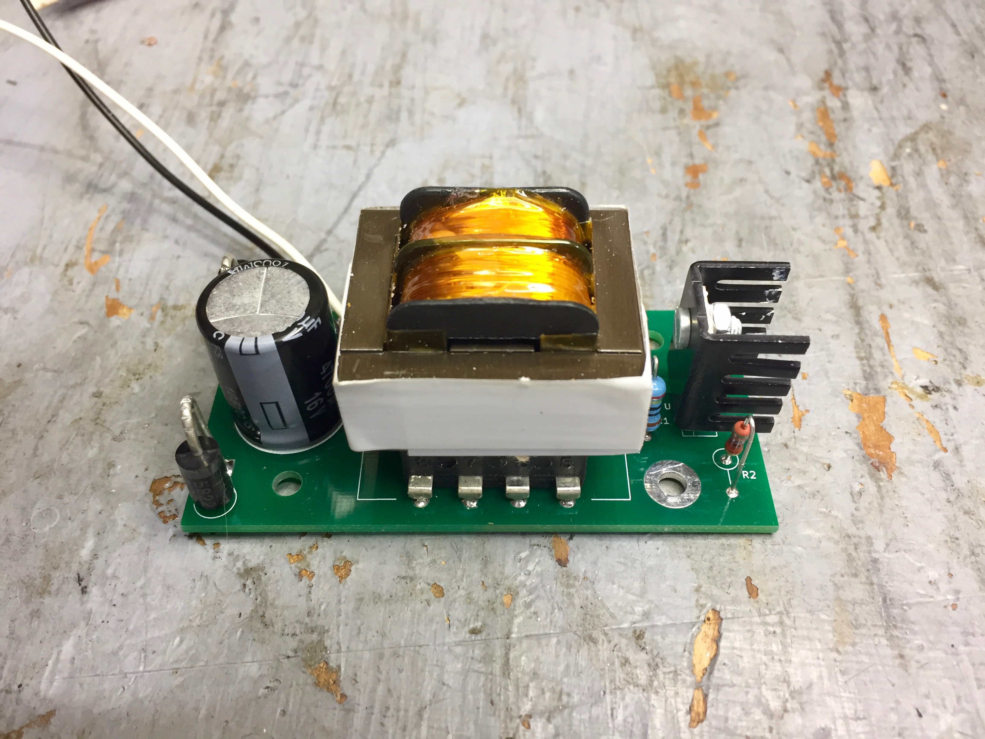
The VTVM battery eliminator uses its own power transformer, so it doesn’t load the original Heathkit power transformer at all.

The transformer is a Triad FS12-200-C2. I bought it from Mouser.

It’s just a simple LM317 circuit.

I wired the two secondaries in series as a 6.3-0-6.3 volt center-tapped transformer, and used two 1N5822 Schottky diode rectifiers to make a full-wave rectifier feeding about 6 volts to the filter capacitor.

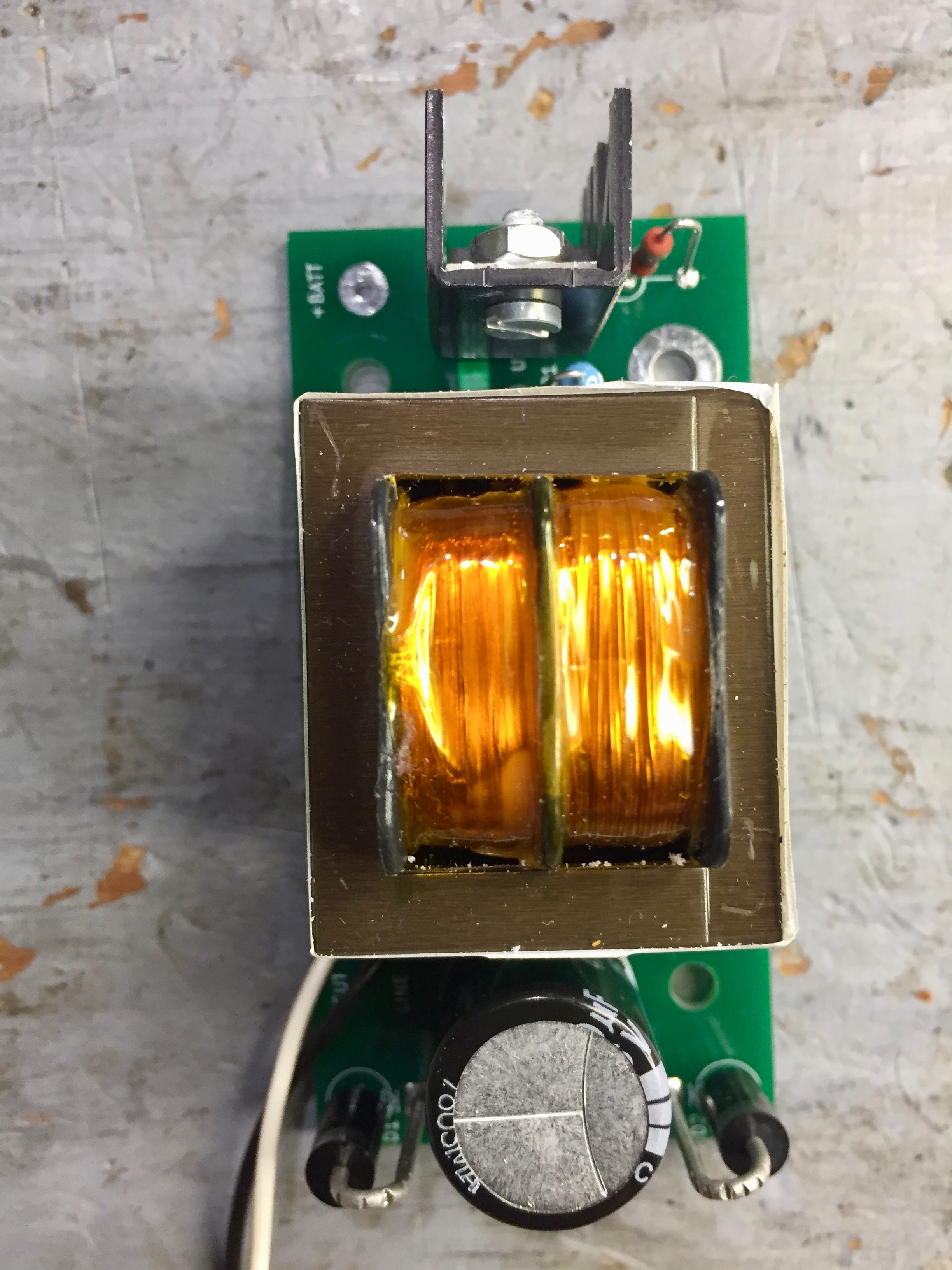
The filter capacitor is grossly oversized. I bought a batch of 4700 µF 16 volt electrolytics some time ago for this project. I must have slipped a decimal point, 470 µF would have been more like it. If I had to do it over again, I’d use a 680 µF to give a little more margin, as the minimum capacitance needed to keep the LM317 in regulation is 466 µF.

Here’s the schematic. I used KiCad on my Mac to draw the schematic and lay out the board. The schematic drawing tool is much clunkier than the defunct but sorely-missed DesignWorks package from Capilano Computing. The PC layout editor is also a bit clunky, but the package is usable. KiCad does have an excellent set of libraries.

Here I’ve mounted the completed board to the standoffs.

The left standoff connects the battery eliminator to the chassis ground, so I used internal star lockwashers on all three mounting screws.

There’s plenty of room for the battery eliminator.

The positive output connects to the resistance section of the range switch.

The battery eliminator picks up the unswitched side of the line from the terminal strip for the line cord.

It connects to the switched side at the same terminal as the VTVM power transformer.

I also completed another switchable VTVM probe for the IM-13.

I use a 1/4 inch stereo (tip-ring-sleeve) phone plug with the ring unconnected to give a little extra insulation between the probe tip and the instrument ground.

Fitting both the RG-58A/U and the Belden test lead wire through the shell of the 1/4 inch phone plug is a tight squeeze. This time, I tried filing a recess to pass the ground lead. It worked out well.
Calibration:
Calibration is a lot of boring knob-twisting. Setting the calibration points is quick and easy, given a meter calibrator and an accurate and precise DMM. But verifying each range is tedious. Here’s how my IM-13 came out, after the restoration.

Everything is well within Heathkit’s specified tolerance.