

I've been working on restoring an Eico 315 signal generator.
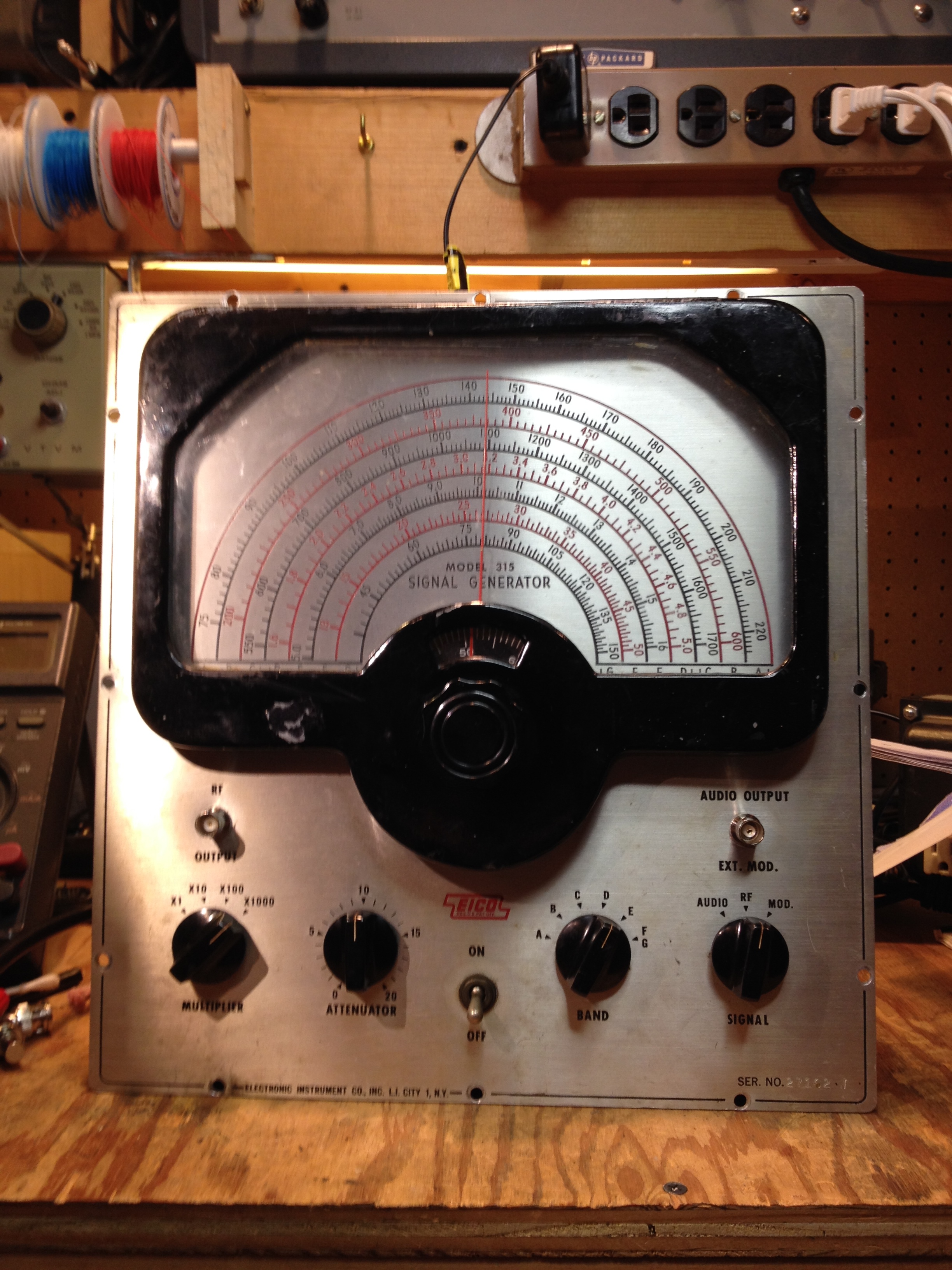
The dial mechanism has a nice vernier reduction gearing and long scales.

The generator is well-shielded with a copper-plated steel chassis.

I used a C-clamp and a length of 1x2 pine to improvise a chassis stand.

I've already given the circuit a partial cap-ectomy; there were two large paper caps next to the choke near the center of the chassis.

I removed the line cord and later replaced it with a three-wire cord with the ground lead connected to the chassis. The coil on the black phenolic form at the left forms a line noise filter along with the line bypass capacitor. I replaced the original across-the-line paper cap with a type X safety cap, the blue cap on the left.

A few of the resistors had drifted out of spec, for instance this 1K Ω 1W resistor in the power supply voltage regulating circuit,

and this 68K Ω grid resistor on the 6SL7 audio oscillator. I replaced them both. The rest measured within their specified tolerance.

The power supply uses a two-section electrolytic filter cap. I'm sure it's bad and in need of replacement.

I disconnected the old filter caps and removed the wires ...

... and then installed two modern radial-leaded electrolytic caps.

It was a little difficult to get to some of the paper capacitors and install replacements ...

... but I managed.

The output attenuator is in its own shielded compartment. When I removed the cover I saw that one of the 100 Ω resistors in the L-pads had been smoked. It was burnt completely in half. The other resistors were fine so I left them in place. I also replaced the Amphenol 80-75 series jack (still available from Switchcraft as their part 2501MP) with a chassis mount BNC connector.

I also replaced the audio output Amphenol connector with a BNC and re-wired it to feed high-level RF tapped off ahead of the output attenuators. It was hard to reach through the maze of wires and components at the lower left of this photo to loosen the mounting nut for the audio connector and tighten the nut on the new BNC connector.
I didn't intend to do a cosmetic restoration, but if you look closely at the first photo, you'll notice that the fiducial line for the vernier scale is off-center. The dial glass had broken loose and shifted a bit while I was working on the generator. I tried to shift it back into place but just managed to make things worse, so I was committed to taking the dial bezel off.

When I removed the dial bezel, some more of the already-chipped paint flaked off, so now I was into refinishing the bezel. I'm still working on getting the paint off. I started by scraping along with some heat from a heat gun, but there's still a lot left. I don't want to use chemical strippers or solvents because my wife is very sensitive to the smell, and a steel wire brush would scratch the aluminum casting. So I guess I'm left with some more tedious scraping before I can repaint the bezel.

I also removed the knobs and cleaned up the front panel with Gojo.

I used Gojo on the knobs, too, along with a toothbrush to get into the crevices.

It's not perfect but it looks much better.
I then tried to calibrate it. Most of the bands were close to begin with and were easy to tweak even closer with my counter, but band C gave me trouble. The alignment frequency for band C is 1600 kHz and I couldn't get the frequency down below about 1650 kHz, even with the trimmer fully meshed. I ended up adding a 22 pF mica capacitor in parallel with the band C trimmer. This got the generator down to 1600 kHz, but the low-end tracking is still pretty poor:

The other bands are fine, it's just band C that is off.

I examined the coil but couldn't see any damage. It's the coil on the right in the above photo.

Here's a photo of the other side ...

... and from the back ...

... and the front.
From the poor tracking, it looks like the band C coil has too little inductance. Has anyone come across this before? Is it a manufacturing glitch? Some subtle damage to the coil? Something else? I'm out of ideas myself, except that at some point in the future I might try adding some series inductance to the band C coil.
Update:
This tracking error bugged me enough that I unsoldered the band C coil and took some measurements. I first tried using my Heathkit IB-5281 R-L-C bridge, but the ambient AC noise at my bench is too high to use it with test leads. The IB-5281 doesn't have a tuned detector, so noise pickup on the test leads can obscure the null. So I resorted to one of those $20 Chinese transistor-resistor-capacitor-inductor component checkers based on the open-source Transistor Tester with AVR Microcontroller designed by Karl-Heinz Kubbeler. (Here's a link to the English-language documentation.)
The checker doesn't measure small capacitances, so I couldn't measure the tuning capacitor when set for 1600 kHz. But I was able to measure it when set for 600 kHz - it was 360 pF. The band C coil measured 160 µH. Adding in margin for the trim capacitor and stray capacitance from the wiring, I figured the total capacitance would be about 380 pF. To resonate 380 pF at 600 kHz takes about 185 µH, or about 25 µH more than the band C coil.

I dug around in my parts bins and came up with a bag of 27 µH inductors that I bought from Dan's Small Parts. There wasn't room for a terminal strip to mount the extra inductor, so I just hung it in space.

The bus wire from the trim cap is pretty stiff, so it's not too bad, but I'm sure band C will be a little microphonic now.
I fired up the counter and the generator and trimmed the band C trimmer for 1600 kHz, then turned the dial down to 600 kHz. The counter read about 604 kHz. Success!
I let the counter and the signal generator warm up for a few hours, then re-checked the dial calibration:

Looks good to me!
Another Update
I finally removed the paint from the bezel using 3M Safest Stripper. It worked nicely and with no objectionable odor.

I filled the pits in the casting with auto body spot putty and wet-sanded it down with 600 grit wet-or-dry sandpaper.
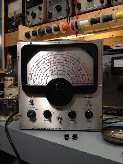
Then I gave it a couple of coats of Krylon gloss black and waited a few days for the paint to cure. Then I reinstalled the bezel and dial glass.
The output level multiplier knob just broke in half while I was working on my Nikko 719, so I installed a temporary replacement. I'll epoxy the original knob back together and hope it holds. Maybe I should swap it with the attenuation knob, since that knob doesn't get as much stress since it's only adjusting a pot.